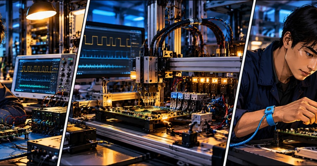
Hardware-in-the-loop (HIL) testing is a method of validating embedded software while it runs on actual electronic hardware. A computer directs a physical device through repeatable test conditions, measures how it responds, and records the results. Unlike a test that merely compiles firmware or simulates a microcontroller, a hardware-in-the-loop test can expose faults arising from real timing, pins, sensors, memory, electrical interfaces, and reset behavior. The central engineering challenge is designing experiments that remain meaningful, safe and repeatable across firmware revisions.
The Firmware Engineer curriculum advances from firmware observability, structured event logs and timing to controlled verification. Earlier material explains fault handling and post-mortem architecture, hardware debugging with JTAG, SWD, OpenOCD and GDB and RTOS synchronization. Those capabilities reveal and diagnose faults; hardware-in-the-loop engineering turns expected system behavior into measurable automated tests.
Elementary Overview
A computer program may seem correct on a laptop but behave differently inside a small electronic device. A temperature sensor, motor controller or radio has real wires, voltages and timing limits. Hardware-in-the-loop testing connects the device to a test bench that can send commands, imitate certain inputs and check outputs. The bench can repeat the same experiment after every software change and report whether the device behaved as expected.
A useful comparison is testing a car’s dashboard with a controlled test rig before driving the finished vehicle. The rig checks what the dashboard displays when different signals arrive. It does not replace testing the complete car, but it finds problems earlier. Similarly, a firmware test rig proves selected behaviors of a real board without claiming to reproduce every condition the final product will encounter.
The device under test and its surrounding equipment
The device under test (DUT) is the development board or product being examined. A basic HIL bench includes a host computer, stable power, programming or debug access, a communication channel for logs, and a test harness that controls stimulus and checks results. Depending on the requirements, the bench may include a relay board, logic analyzer, oscilloscope, programmable power supply, sensor emulator, network peer or a second DUT. Each component adds capability and another possible source of measurement error.
The test engineer establishes a known starting state before collecting results: board revision, firmware binary and hash, bootloader version, configuration, calibration, peripheral wiring, power limits, fixture identity and ambient conditions when those affect the test. A pass on one board does not establish that a second board or production batch will behave identically. Variation in component tolerances, oscillators, connectors and interfaces must be considered in the coverage plan.
Levels of embedded firmware testing
Unit tests verify small functions and classes with controlled inputs. Integration tests verify interactions among modules, drivers or protocol stacks. System tests check functions of an integrated device. HIL tests place some or all of those checks on actual target hardware. The terms describe different dimensions: a HIL test can exercise one driver or an entire application. Build-only checks, host simulation, emulation, HIL execution and field evaluation provide different evidence, not interchangeable success labels.
For example, a mocked SPI driver can demonstrate that a message-building function supplies the expected bytes. A physical HIL test can additionally show that the bus clocks, chip-select timing, peripheral responses and real electrical signals satisfy the application’s requirements. For CAN bus firmware, a second physical node may expose frame arbitration, bus-off behavior and timing effects absent from an isolated software test.
Zephyr’s Twister test runner
The Zephyr Project maintains Twister, a test runner that discovers test scenarios, builds application variants, executes eligible tests and produces reports. Its official documentation distinguishes a successfully built scenario from one that actually ran. A green compilation result proves a build succeeded; it is not evidence that a peripheral worked on a physical board. Twister can use emulation, native simulation and device testing, subject to the target platform and runner capabilities.
A typical Zephyr workspace can inspect available testing options with west twister --help. An explicitly configured lab may generate a hardware inventory using west twister --generate-hardware-map map.yml, review and correct the detected board information, and run applicable tests with west twister --device-testing --hardware-map map.yml -T tests/drivers. This is a documented form of invocation, not a universal production command: the path, platform, permitted flashing, serial port and board runner must be chosen for the specific authorized DUT.
The Ztest framework supports assertions, setup and teardown, fixtures, repetition and randomized execution order. A test assertion converts a requirement into a measurable condition. A temperature driver, for instance, might be required to reject an out-of-range input and raise a defined error; the test must stimulate that condition and inspect the returned state rather than infer correctness from the absence of a crash.
A hardware test bench in practice
The Zephyr Project’s hardware-in-the-loop Tech Talk, featuring Mike Szczys of Golioth, demonstrates a practical approach to integrating physical devices with a software-development workflow. The discussion connects firmware testing to repeatable automation and self-hosted CI execution.
A well-designed test fixture prevents accidental connection to the wrong DUT, limits current and voltage, and identifies exactly which cables and peripherals are attached. Where a relay or programmable supply can remove power, the test must provide a safe fallback state. Automated testing does not make an unsafe circuit safe: bench operators should follow equipment ratings and approved handling procedures, especially when motors, batteries, high current or mains-powered devices are involved.
Pytest, device fixtures and reproducibility
Twister can delegate test execution to pytest through a supported harness. The official pytest harness reference describes a dut fixture providing a common interface to a real device, native simulation or certain emulated targets. A test can wait for known serial output, inspect response messages, and produce a clear pass or failure. Reusing a common interface improves portability, but a simulated test must still be labeled as simulated in the report.
A simplified educational test might wait for a device’s known ready message: def test_startup(dut): dut.readlines_until(regex="APP_READY"). The actual log pattern, timeout and harness setup are specific to the application. The assertion demonstrates that the expected serial message appeared; it does not prove that the physical sensor, network or actuator passed a separate health check. Better tests validate measurable externally observable behavior as well as diagnostic text.
When multiple boards participate, Twister’s multi-DUT facilities can reserve more than one device and pass them to pytest, provided the chosen execution environment supports the configuration. A hardware map records the platforms, serial connections and fixture associations so that physically connected peers are paired correctly. The Zephyr pytest integration documentation provides the device-adapter model. Stable device IDs and fixture wiring are essential; relying on whichever USB port enumerated first can silently cross-connect test results.
Fault injection and edge-case verification
Fault injection deliberately introduces a specified adverse condition to determine whether firmware detects and handles it. Examples include a simulated sensor disconnect, incomplete serial packet, transient communication loss, full message queue, controlled reset during a write, or an approved power-interruption test. Each experiment must define a precondition, a controlled stimulus, an expected response and objective evidence. A successful test demonstrates handling of that injected scenario only; it does not prove a device is immune to all faults.
A watchdog test must distinguish intentional restart from a crash loop. An interrupted-update test must establish whether the intended boot image is retained or restored, a topic developed in MCUboot Test Upgrades and Recovery Validation. For an RTOS application, randomized scheduling or forced contention can expose problems in semaphores, mutexes and inter-task synchronization. Firmware event logs and timing measurements should capture enough detail to distinguish the cause of a failure from the later symptoms.
Electrical fault injection requires additional discipline. Do not short signal lines, defeat protections, or alter high-energy power paths simply to reproduce a failure. Where a test requires brownout or power interruption, use a manufacturer-approved programmable supply, defined ramp limits, independent current protection and a recoverable test setup. Capture voltage and reset cause together so the evidence identifies the actual stimulus instead of relying solely on a software timestamp after restart.
Continuous integration and release gates
A continuous integration (CI) system can schedule a sequence of checks when firmware source changes. A sensible progression performs static analysis and fast host tests first, builds target configurations next, runs emulated or native-simulation tests where supported, and reserves scarce physical boards for tests that need real hardware. Longer soak tests, release-image validation and unusual environmental tests can run separately. The rule is to match each gate to a concrete engineering risk, not to equate more test cases with better evidence.
At Open Source Summit Europe 2025, Maciej Perkowski described a test strategy for Zephyr spanning Twister, Ztest, pytest, CI and hardware coverage. The discussion illustrates why large combinations of architectures, boards and configurations require deliberate prioritization instead of trying to execute every possible test on every commit.
A release gate should distinguish pass, fail, not run, skipped, blocked and infrastructure error, using the actual runner’s supported status model. The Twister status documentation explains its case, suite and instance reporting. A missing DUT or broken lab cable should not be treated as successful product behavior, and a flaky test should not be quietly deleted from the release evidence. Track repeatability and investigate whether failures correlate with specific boards, versions or environmental conditions.
Worked example: validating a data-center sensor board
Consider a hypothetical controller that reports cabinet temperature over a wired network. The engineering requirement is that the device must reject an out-of-range sensor reading, report a diagnostic condition and recover when a valid value returns. A host simulation can test the conversion and error-handling functions; a hardware fixture uses a supported signal emulator or controlled sensor source to supply defined values to the actual board. A network test client checks the published reading and error flag, while a separate logger records the board’s boot and error events.
Suppose the acceptance rule requires the error state to be reported within 500 ms after an invalid input. If a controlled test measures delays of 310, 340 and 520 ms, the third observation violates the requirement. The longest of those measurements is 520 ms, so an average shorter than 500 ms cannot justify a pass if the requirement applies to each event. The test report must specify the timing reference, sample size and uncertainty; real requirements should be established by the product design, not copied from this illustrative example.
A device that passes normal readings but fails its fault-recovery case should be rejected for that acceptance scenario. The engineer correlates timing measurements with task scheduling and preemption, DMA-driven data transfer and reset/fault records before making a corrective change. This keeps the lesson distinct from simply troubleshooting an already-failed field unit: HIL engineering produces a reproducible experiment that can prevent a recurrence before deployment.
Scaling physical test coverage
Automated benches can be multiplied, but coordination becomes more difficult as the fleet grows. Shared networks, USB controllers, RF interference, firmware versions, fixture wear and log collection can introduce failures unrelated to an application defect. The test controller should reserve a specific DUT, record which firmware was flashed and preserve its output alongside the verdict. A test that is reproducible in software may still be unreliable when physical wiring or radio conditions are uncontrolled.
A 2025 conference presentation on testing Zephyr Bluetooth devices at scale documents a Raspberry Pi–based device farm, continuous testing and real-device fault investigation. It offers a concrete example of why fast simulations and longer hardware tests complement one another rather than compete.
The engineer’s goal is traceability. Test results should connect a requirement, firmware commit, toolchain version, board revision, test script, fixture configuration, stimulus, measured output and report. A flaky test that fails intermittently may be caused by genuine race conditions, insufficient settling time, uninitialized test state or unstable lab infrastructure. Re-running until green without preserving failures hides useful evidence. A defensible investigation records all attempts and classifies the underlying cause.
Review and practical exercises
A useful practice exercise is to write a test specification for a microcontroller that must enter a safe state when a sensor stops responding. Define the DUT, stimulus, observed output, response-time limit, allowable test equipment, power and reset handling, and evidence to preserve. Next, describe which requirements can be tested on a laptop and which require a physical board. Finally, identify how the test would report an unavailable DUT without falsely issuing a pass.
Knowledge check: Why does a successful firmware build not prove real-device operation? What is the difference between a unit test and a HIL test? Which equipment could verify that a GPIO actually changes voltage? Why should a test record board revision and fixture identity? What distinguishes an infrastructure failure from an observed application failure?
Answers: Compiling verifies that code was built, not its electrical behavior. Unit testing describes functional scope, whereas HIL describes the use of physical hardware; they may overlap. A properly rated logic analyzer or oscilloscope can measure GPIO transitions. Board revision and fixture identity make test results reproducible and comparable. Infrastructure failures indicate the test environment could not establish a valid verdict, while application failures are observed deviations under a valid test setup.
Elementary Conclusion
Hardware-in-the-loop testing helps engineers check real electronic products with repeatable experiments. The computer asks the device to do something, the test bench measures its response, and the result is saved. A test is strongest when its expected result is clear and the equipment is known to be working. This process catches problems that a simulation or successful code compilation might miss.
No single bench can recreate every possible situation. Reliable firmware engineering combines small software tests, simulation, physical measurements and tests of the full product. Good test records make problems easier to reproduce, fix and prevent when future firmware versions are released.
References and further reading
Technical references: Zephyr Project — Twister Test Runner; Zephyr — Pytest Harness; Zephyr — Ztest Framework; Zephyr — Test Status Definitions; and Zephyr Developer Summit Testing Presentations. The lesson is a framework-level engineering explanation; equipment-specific actions should follow the product’s documented safety and test procedures.
BitcoinVersus.Tech
Independent technical education from BitcoinVersus.Tech. Follow BitcoinVersus.Tech on X for technology reporting and research.
BitcoinVersus.Tech Editor’s Note: We volunteer daily to ensure the credibility of the information on this platform is Verifiably True. If you would like to support our work and help further secure the integrity of our research initiatives, please scan the QR code below to donate 5,000 sats.
For best results, display the QR code on a laptop or larger screen and scan with a compatible Bitcoin wallet on a second device. Confirm the Bitcoin address before sending: 3C9o19EH5HSiwEPyCTmEKzxhNCbo2X6TTb.

BitcoinVersus.tech is not a financial advisor. This media platform reports on financial subjects purely for informational purposes.


Leave a Reply