
A memory protection unit (MPU) is a hardware feature that checks whether the processor is permitted to read, write or execute instructions at a given memory address. In embedded firmware, an incorrectly calculated pointer, runaway task or corrupted stack can damage important state long before the original programming mistake is obvious. An MPU can turn some of these silent corruptions into detectable access faults. This Firmware Engineer course entry is cataloged as OSFEC.014. It follows hardware-in-the-loop firmware testing, connecting the design of protection rules with repeatable validation on a real microcontroller.
The objective is not to suggest that every Cortex-M chip has the same MPU or that turning one on makes firmware secure. This lesson distinguishes hardware permissions from operating-system isolation, explains what an access violation can tell the engineer, and develops a measured lab workflow. The most authoritative starting point is STMicroelectronics application note AN4838, Revision 11, March 2026, supplemented by the exact processor programming manual and the installed RTOS documentation.
Elementary overview
A microcontroller is a small computer on a chip. It may hold instructions in flash memory, working variables in SRAM, and hardware-control registers at fixed addresses. Without properly configured protection, software that computes the wrong address can access memory intended for something else. In an industrial control board, for example, a sensor task might accidentally overwrite a data buffer used by a safety-monitoring function. Even if the processor keeps running, the resulting output may be wrong.
The MPU is like a set of guarded zones in that address space. It does not move bytes, translate virtual addresses, increase physical RAM or substitute for a memory management unit (MMU) in a desktop operating system. Instead, it examines accesses made by the processor and applies programmed permissions. A rule can prohibit execution from a data buffer, prevent an unprivileged task from altering kernel memory, or deny access to a stack guard. Supported features vary by core, device implementation and processor mode.
Which memory can be protected?
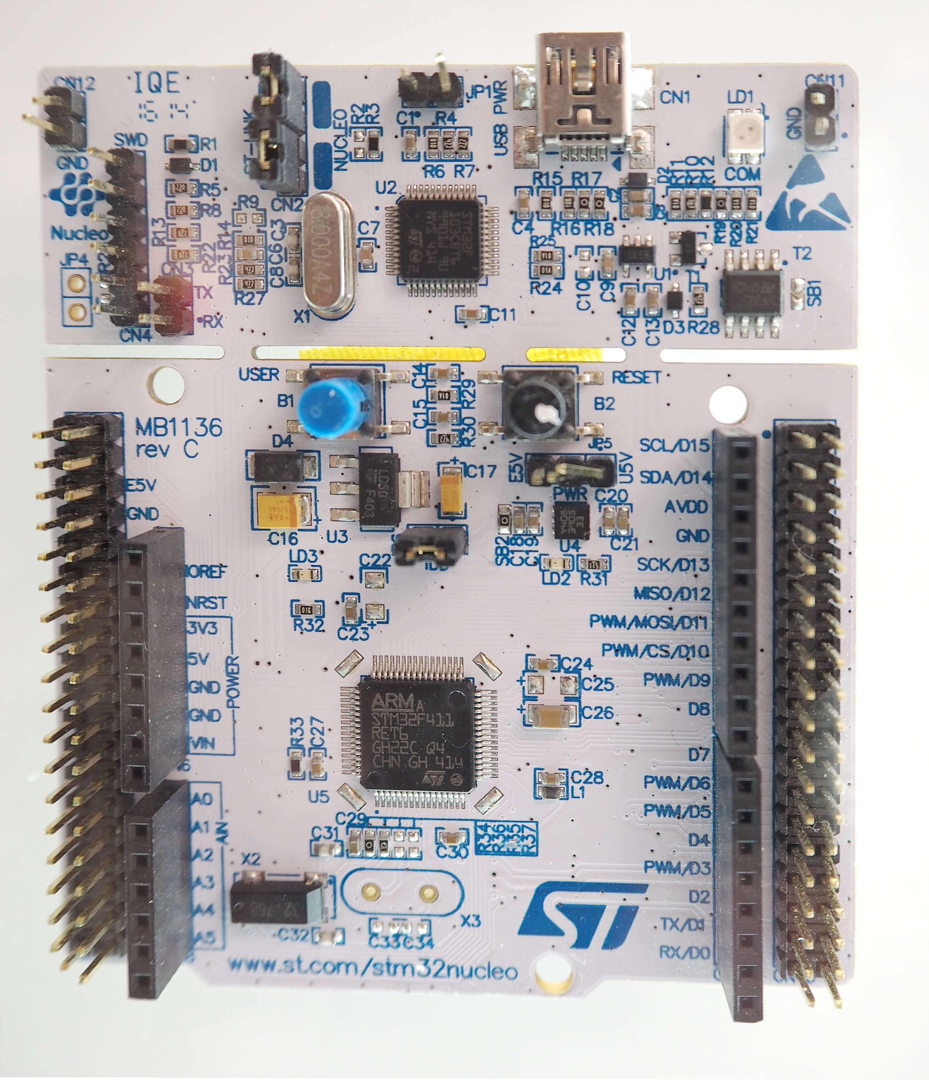
Firmware engineers begin with the linker map, the microcontroller’s reference manual and the memory architecture. Common sections include .text for program instructions, .rodata for constant data, .data for initialized writable variables and .bss for zero-initialized storage. Stacks, heaps, shared buffers and peripheral registers need separate consideration. Those sections do not automatically become individual MPU regions: the linker layout and protection granularity must be compatible with the hardware.
The key permissions are read, write and execute, together with processor privilege. Execute Never (XN) means an instruction fetch is prohibited even if data reads are allowed. Memory attributes such as Normal versus Device and cacheability also matter. Incorrectly marking peripheral registers as ordinary cacheable memory can produce dangerous behavior. Engineers should never copy a region table between MCU families without validating these constraints.
| Memory area | Illustrative access policy | Why |
|---|---|---|
| Application flash text | Read, execute; no ordinary writes | Run approved instructions without unintended modification |
| Read-only constants | Read-only, execute-never where separately representable | Protect lookup tables and immutable parameters |
| Application SRAM | Read/write, execute-never | Permit variables while preventing instruction fetches from data |
| Peripheral register window | Restricted privileged access, Device type, execute-never | Avoid accidental register edits and improper memory ordering |
| Kernel/private RTOS state | Privileged access only | Keep untrusted tasks from corrupting scheduling and system control |
| Task stack guard | No access, where supported | Detect growth into a prohibited address range |
For some Armv7-M MPUs, region sizes follow power-of-two and alignment restrictions; priority and eligible subregions can matter when regions overlap. Newer Armv8-M implementations use base-and-limit region definitions with different rules. ST’s AN4838 explicitly separates these architectural families. The table above is deliberately conceptual: it is a security policy to translate into device-specific code, not a literal configuration register dump.
How a Memory Protection Unit works
When the core attempts a load, store or instruction fetch, the MPU compares the access address with its configured regions and the executing code’s privilege level. A permitted access proceeds normally. A prohibited instruction or data access can raise a MemManage fault on applicable Cortex-M devices. If configurable fault handling is disabled or a fault escalates, the observable event may be a HardFault instead. Engineers must examine the actual exception state rather than assuming every firmware crash originated in the MPU.
This video explains why STM32 firmware uses memory regions and access permissions. The second half of the lesson applies the concepts to an RTOS with isolated tasks.
Video: ControllersTech — STM32 MPU Config: Need for the Memory Protection Unit (July 2021). Relevant introduction to MPU motivations and memory-region protection.
In practice, the desired outcome is fault containment, not merely an exception message. The protection policy should stop a malfunctioning component from silently damaging unrelated state. It should also preserve enough diagnostic information to understand what happened. There is no guarantee that a corrupted privileged task can be safely restarted. Systems with hazardous physical outputs must enter a verified safe state if execution integrity is in doubt.
Permissions, privilege and trust boundaries
On supported Cortex-M systems, privileged firmware and unprivileged application code can have different memory-access rights. A kernel may need privileged access to interrupt-control registers and scheduling structures, while an application thread should see only its stack, executable code, approved shared buffers and explicit interfaces. The separation is more useful when the operating system enforces it consistently: user tasks call validated system services instead of manipulating privileged control blocks or peripheral registers directly.
Some processors have a privileged default-background-map option, often named PRIVDEFENA. Depending on the configuration, privileged code may be able to access addresses without an explicit MPU region while unprivileged code cannot. This flexibility can also conceal gaps in the intended isolation policy. The implementation must test both permitted and denied operations in the actual privilege modes that will run in production.
Protecting real-time operating-system tasks
An RTOS such as Zephyr can combine processor privilege with memory domains and user-mode threads. In Zephyr’s Memory Protection Design, a user thread has its own stack, code and read-only data plus any explicitly granted regions. Memory partitions let developers share buffers among intended threads without granting blanket access to all SRAM. Protection resources are limited by the MCU’s available MPU regions, so application structure and region allocation are real engineering constraints.
A typical design might isolate telemetry parsing from a motor-control kernel. The telemetry task receives only the packet buffers it needs. The kernel validates any requests that cross into privileged services. A malformed packet must not be able to edit the motor driver’s private state merely because both functions share one chip. This boundary can narrow the impact of a logic bug, but the application must also verify pointer lengths, integer arithmetic, device permissions and the lifetime of shared buffers.
The Linux Foundation presentation below discusses Zephyr’s actual memory-protection design, including physical memory regions, user privileges and RTOS system calls. It is particularly useful for understanding why a microcontroller MPU cannot simply imitate the page tables of a general-purpose operating system.
Video: The Linux Foundation — Zephyr OS Memory Protection, Andrew Boie (May 2020). Presentation on RTOS userspace, protection domains and hardware MPU limitations.
Engineering the boot-time protection sequence
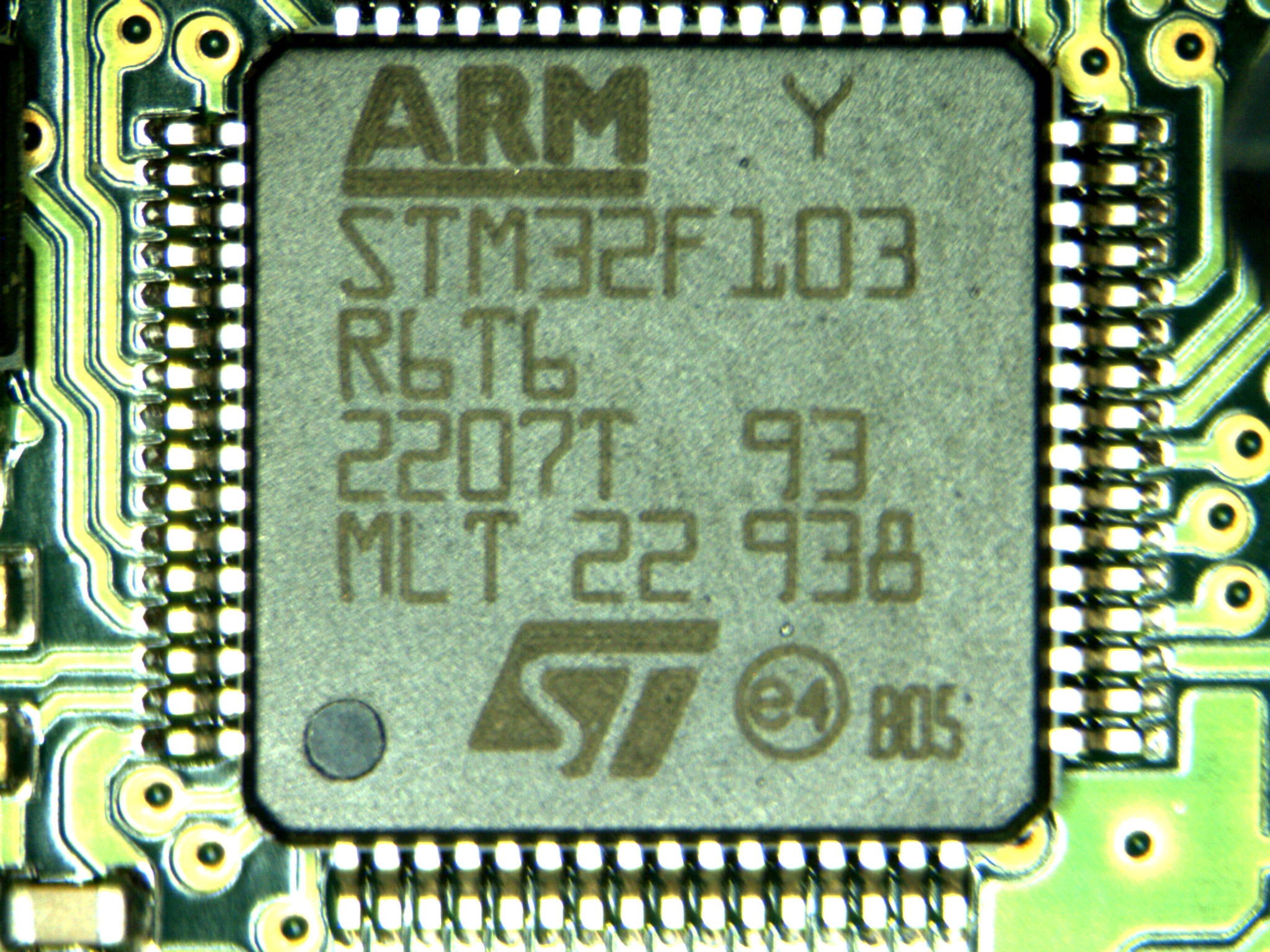
Protection should be designed before it is enabled. Capture the board revision, exact MCU marking, compiler/linker configuration, bootloader address map, stack placement, RTOS task layout, interrupt execution model and DMA design. Confirm that the target device actually implements an MPU and identify the number of usable regions. Validate the flash and SRAM boundaries with the device manual; a development-board marketing description alone is insufficient.
- Plan the address map: identify executable flash, constants, data, per-task stacks, peripherals, shared communication buffers and any memory-mapped external devices.
- Define least-privilege policy: document which tasks may read, write or execute each area and which operations require a trusted service call.
- Program architecture-specific regions: honor required alignment, region priority, size and memory-type constraints. A Cortex-M4 configuration is not automatically valid on Cortex-M33.
- Prepare fault diagnostics: enable applicable configurable fault handling, save registers in a safe way and define a non-reentrant reporting path.
- Enable with required synchronization: use the processor and vendor-recommended barrier sequence so changed protection state is recognized before code continues.
- Test on isolated hardware: use a protected bench fixture and a known-good recovery image before introducing deliberate denied accesses.
The following is pseudocode only. Its function names are descriptive, not CMSIS or STM32 HAL APIs. Production code must use the exact processor instructions, CMSIS definitions and vendor libraries for its target, and every mapping must be reviewed against the linker output.
// Teaching pseudocode — not a vendor driver or drop-in application
on_boot:
    verify_target_mcu_and_MPU_presence()
    examine_linker_map_and_required_boot_memory()
    configure_flash_for_instruction_fetch_without_app_writes()
    configure_application_sram_read_write_execute_never()
    configure_peripheral_windows_as_device_execute_never()
    restrict_kernel_state_and_assign_task_private_stacks()
    enable_architecture_appropriate_MemManage_diagnostics()
    apply_required_memory_barriers_and_enable_MPU()
    run_prepared_permitted_and_denied_access_tests()
    record_fault_status_and_restore_known_good_firmware()
Fault registers and post-mortem evidence
For the applicable Cortex-M fault model, the configurable fault status register (CFSR) contains MemManage status bits. IACCVIOL indicates an instruction-access violation; DACCVIOL indicates a data-access violation; MMARVALID tells the debugger whether the MemManage fault address register (MMFAR) contains a valid address. Other status bits cover errors during exception stack entry, return or lazy state preservation. Not every fault populates the address register, and the stored address must never be used blindly when the valid bit is clear.
Preserve the faulting program counter, link register, stacked xPSR, processor privilege state and the applicable fault status. Correlate these with the firmware build ID and linker map. A crash address alone is not a root-cause explanation: determine the exact instruction and whether the address was supposed to be accessible. Memfault’s Cortex-M HardFault debugging guide provides register-by-register context. The preceding lesson on structured observability explains why durable event identifiers and timestamps are just as important.
Practical case study: a sensor task writes into another stack
Imagine a controller with two RTOS threads. A sensor parser accepts framed packets and stores readings in a small buffer. A motor supervisor maintains a private stack and periodically updates a control register. A malformed packet causes an off-by-one write in the parser. Without a suitable memory boundary, the write might alter a neighboring task’s data and trigger a motor-control problem minutes later. With well-designed MPU isolation, an unprivileged parser attempting an out-of-domain write should produce a memory-access fault instead.
The engineer first checks the task’s allowed memory domain and the exact address of the failed write. If the fault status shows a data access violation, the recorded faulting instruction maps to the parser, and the attempted destination belongs to the motor supervisor’s private stack, the evidence supports the isolation mechanism working as intended. The correct next step is to fix the parser’s bounds checking and retest—not to enlarge the parser’s permissions until the crash disappears.
A second test puts a deliberate guard region beyond a task stack. The RTOS may detect growth into the guard when it crosses that boundary, depending on the stack allocation and MPU behavior. Such a guard does not detect every out-of-bounds write, and features such as Zephyr’s optional CONFIG_HW_STACK_PROTECTION impose platform-specific limits. The test must target a spare board or development emulator with verified recovery access, not equipment currently controlling motors or industrial loads.
What the MPU does not protect
- DMA writes: a CPU MPU is not normally a general memory firewall for independent bus masters. DMA engines may still write locations the CPU would be prohibited from accessing. Use DMA design controls, bus protection or an IOMMU where the hardware provides one.
- Privileged code defects: overly permissive privileged regions and unsafe system-call interfaces can defeat the intended boundary. MPU isolation is a layer, not proof of a secure kernel.
- Fault-free control outputs: a detected memory violation can still leave a relay, power stage or actuator in a hazardous state. Define and validate fail-safe actions.
- Flash-image authenticity: secure boot, cryptographic image verification and update rollback protections solve different problems. Connect this to firmware image integrity verification.
- Functional verification: a few deliberate fault tests do not prove all regions are correct after every RTOS task switch or future firmware update. Keep repeatable hardware-in-the-loop regression tests.
A repeatable laboratory validation checklist
- Record the device part number, bootloader version, clock configuration and exact toolchain/build ID.
- Capture the linker map and show that stack boundaries and region alignments meet the target’s MPU restrictions.
- Verify intended read, write and execute operations in each applicable privilege mode before testing denied access.
- Introduce one controlled bad access at a time: an unprivileged write to privileged memory, an attempted fetch from an XN data region, and—if supported—a guarded stack overrun.
- Log
CFSRand applicable fault-address state, the instruction location, task identity and whether fault handling was enabled. Check escalation behavior if the configurable exception is absent. - Confirm safe fallback and debugger recovery, restore the approved firmware, and compare the recorded result with the expected test matrix.
- Add each confirmed failure mode to the HIL suite from the preceding Firmware Engineer lesson.
Knowledge check
- Why is an MPU different from a general-purpose MMU, and why does the distinction matter on a microcontroller?
- What does an Execute Never rule protect against?
- Why should software check
MMARVALIDbefore interpretingMMFAR? - Why can a DMA transfer still damage a buffer that a CPU task is not allowed to write?
- What would demonstrate that isolation is effective after a firmware update or an RTOS context switch?
Answers: An MPU enforces configured permissions on addresses without generally providing virtual-memory translation. XN rejects instruction fetches from protected data regions. The MMFAR address is not guaranteed valid without its status bit. A separate DMA bus master may bypass the CPU MPU, so other hardware or driver safeguards are required. Repeatable tests should validate both allowed and denied accesses with evidence from the intended privilege modes, representative context switches and current firmware builds.
References and further study
Read STMicroelectronics AN4838, Revision 11 (March 2026); Zephyr Memory Protection Design; Zephyr Userspace Overview; Memfault — Fix Bugs and Secure Firmware with the MPU; and Memfault — Cortex-M HardFault Debugging. Continue in this curriculum with Linker Scripts and Startup Code, RTOS Synchronization, and Fault Handling Architecture.
BitcoinVersus.Tech Editor’s Note: We volunteer daily to ensure the credibility of the information on this platform is Verifiably True. If you would like to support our independent technical education and research, please scan the QR code below to donate 5,000 sats (best results on a laptop or larger screen).

For mobile scanning, open this lesson on a laptop or larger screen and scan the QR code with a compatible Bitcoin wallet on your phone. Confirm the destination address before sending: 3C9o19EH5HSiwEPyCTmEKzxhNCbo2X6TTb.
BitcoinVersus.tech is not a financial advisor. This media platform reports on financial subjects purely for informational purposes.


Leave a Reply