
A missing ASIC-chip report is a diagnostic observation from a Bitcoin mining control board or dedicated hashboard tester: fewer mining chips responded than the firmware expected. The number can be zero, a partial chain, or an apparently complete count despite poor mining performance. In each case, the engineer must separate chip discovery from chip health. A reported missing chip is not necessarily a failed silicon die.
This reference lesson belongs to the Hashboard Repair Engineering curriculum. It follows the anatomy of a hashboard, voltage domains and power distribution, and hashboard signal chains. Its focus is interpreting evidence, assigning a fault to the appropriate subsystem, and knowing when to stop and refer the board for controlled repair.
What you will learn
- Distinguish an absent hashboard from a board that is present but reports zero or fewer-than-expected ASICs.
- Understand why the correct expected count depends on the exact model, silicon generation and PCB revision.
- Use miner logs, maintenance history and compatible test-fixture results to narrow plausible causes without treating an error message as a complete diagnosis.
- Build a safe evidence trail for service escalation, rework authorization and post-repair validation.
What an ASIC count really measures
An ASIC hashboard carries a chain of chips that perform the SHA-256 calculations used in Bitcoin mining. During initialization, the controller communicates with the board and attempts to discover the chips or confirm their responses. The displayed count is therefore a snapshot of detected communication under specific power, clock, reset, software and thermal conditions. A healthy-looking number does not prove every chip can mine valid work at operational frequency.
A classic Antminer S19 BM1398 board typically has 76 ASICs. The S19 Pro’s documented BM1398 implementation has 114 ASICs. Those figures are not interchangeable and do not automatically apply to a board identified only by the marketing name “S19,” let alone to newer S19 XP or S21 variants. Record the silkscreen PCB identifier and validate the applicable repair manual before judging an expected number. See the S19 repair manual and the S19 Pro guide for the differing architectures.
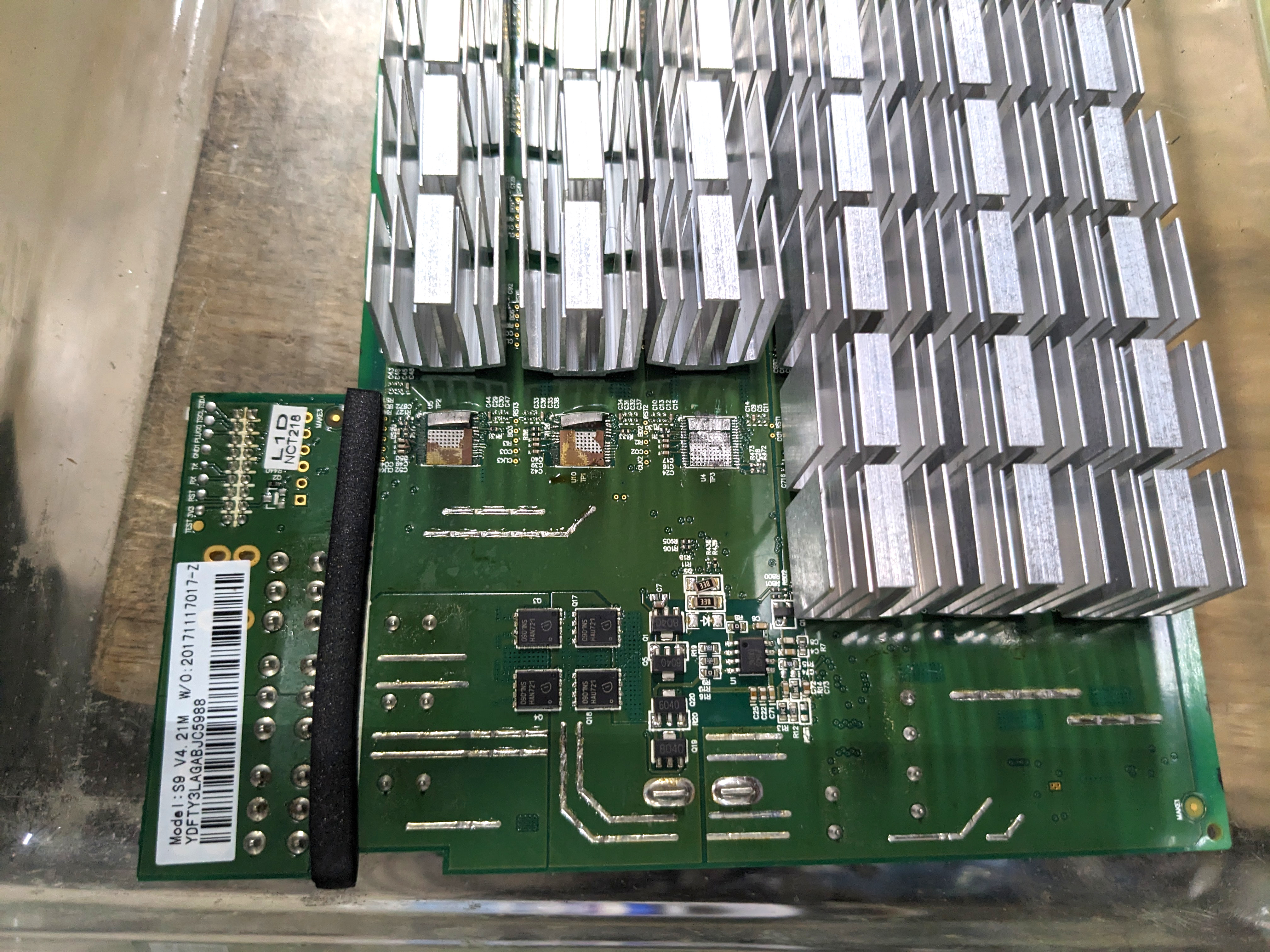
The same physical-looking board family can hide important revisions. A replacement ASIC, tester firmware or fixture cable selected solely by product name may be incompatible. Misidentification can invalidate a test before a technician ever reaches the suspected chip.
Three different symptom classes
- Board not detected: the controller may fail to establish communication with an entire hashboard. Investigate the reported board slot, connector seating, control-board interface, recognized board revision and power state before declaring the PCB defective.
- Zero ASICs on a detected chain: software may report
Chain 0 only find 0 asic. Causes can include insufficient power, a shorted supply domain, missing clock or reset signaling, defective interface circuitry, or an open chain. The exact first failure point is still unknown. - Partial count: a log such as
Chain 0 only find 6 asic, will power off hash board 0means only six chips were confirmed in that scan. The remaining unconfirmed chips are not automatically six separate defects—or proof that the seventh chip’s silicon is bad. A break in the communication path, local power or test setup can prevent downstream responses.
Bitmain’s restart guidance explicitly warns operators not to repeatedly restart a miner when one hashboard reports only some ASICs, because secondary damage may occur. A fleet technician should preserve logs and follow the manufacturer’s service route instead of cycling power until the alarm disappears.
The role of the compatible hashboard test fixture
A dedicated hashboard tester can check chip discovery independently of a production control board, provided the fixture, support cables, test software, voltage source and cooling method have been validated for the exact board revision. Bitmain’s official S17/S19-series test-jig documentation explains why fixture setup and required cooling are part of a valid test. An incorrect test configuration is a possible source of false failures.
Video: ZEUS MINING, “Tutorial for Antminer universal test fixture upgraded version” (July 2025). An original demonstration of a repair fixture using compatible example hashboards. Its settings and connection process are model-specific; observe only unless qualified and following the current manufacturer’s procedure.
The fixture is an instrument, not an oracle. One reported failing chip index may signify the first point beyond which the tester received no valid response. An engineer must still determine whether the cause is a missing domain voltage, damaged passive component, unstable clock or reset, faulty ASIC, physical connector defect or incorrect testing configuration. An observation belongs in the record even when the underlying cause is unresolved.
A safe diagnostic intake workflow
- Record the identity: asset ID, miner model, firmware, control-board revision, hashboard slot, PCB silkscreen identifier, ASIC type, and previously verified chip count. Include any repair history.
- Capture the original evidence: kernel logs, alarms, chain count, hardware version, thermal readings, uptime and frequency/voltage settings before any reboot or firmware modification. Note whether pool and network connectivity are normal.
- Stop on electrical warning signs: burnt connector, liquid ingress, damaged cable, discolored copper, suspected short circuit, smell of overheating, or a partial-chip count. Follow isolation/lockout procedures; do not reconnect a known faulty board to production power.
- Inspect de-energized hardware: after professionally isolating, disconnecting and verifying the unit is safe, inspect cable seating, pin deformation, contamination, damaged heatsinks, loose fasteners and PCB distortion. Follow manufacturer instructions, ESD precautions and site policy.
- Choose the test boundary: a permitted control-cable inspection may resolve a slot communication problem; a questionable PCB or suspected power fault belongs at a qualified hashboard repair bench with suitable approved test fixtures.
- Escalate with evidence: state “chain responds with six of the expected 76 ASICs” rather than “70 bad chips.” Document the exact firmware and tester message, the conditions of the test and what remains unproven.
This workflow is purposely not a live-board probing recipe. Antminer power supplies and board capacitors present substantial electrical hazards, and seemingly simple field tricks such as bridging ASIC test points or modifying power sequencing can damage hardware or injure a technician. Those activities require model-specific instructions, authorization, appropriate equipment and a qualified repair environment.
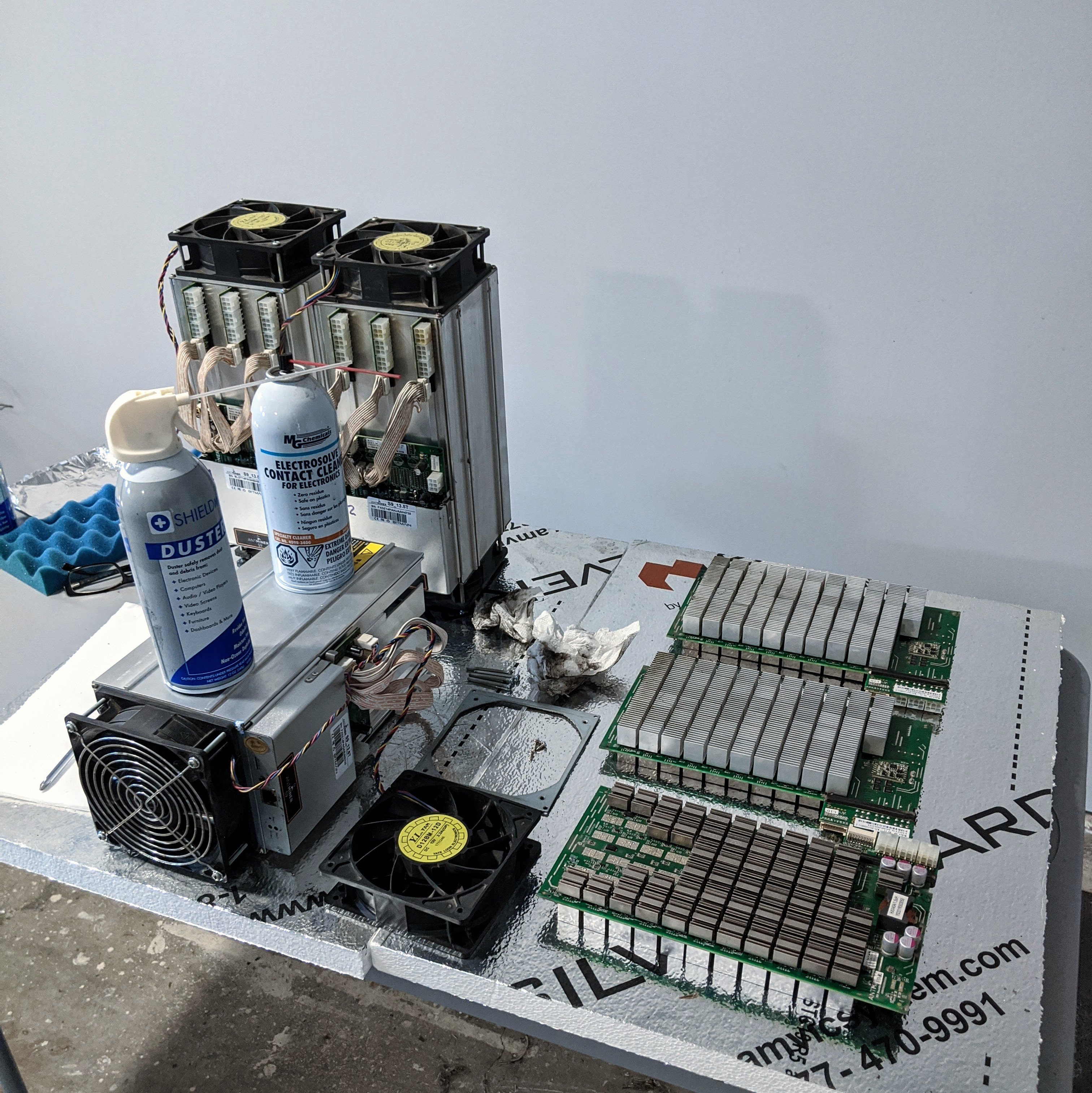
A visual inspection is a necessary first filter, not a guarantee. A clean connector can still have a damaged contact; a visually normal ASIC may be electrically faulty; and an overheating board can have intact-looking chips but impaired airflow. Record what is seen, what is measured and what is inferred as three separate categories.
Practical case: one S19 chain detects six chips
Consider an illustrative 76-chip S19 board that previously worked normally. The system remains reachable over the network, two other boards initialize correctly, but the kernel log reports Chain 0 only find 6 asic, will power off hash board 0. The right first conclusion is incomplete enumeration of chain 0. It is not yet proof that chip seven failed. The machine’s total hashrate may fall, but that does not identify an individual component.
The operator preserves the log and takes the affected unit out of production following the service procedure. The repair intake confirms the PCB revision and prior configuration and inspects the de-energized cable and board. A qualified technician then decides whether to perform fixture-assisted discovery, approved electrical measurements and component-level diagnosis. A chain break near a particular chip could arise from signal continuity, passives, domain supply or chip attachment. The defect is not closed until the chosen corrective action passes a repeatable verification test.
Practical case: every board reports zero ASICs
If three separate boards simultaneously report no discoverable ASICs, one common control, power, firmware or tester condition becomes a plausible cause. However, a common-cause hypothesis is not proof: multiple shorts and simultaneous physical damage remain possible. Bitmain’s zero-hashrate guidance lists power, firmware, network/pool and hashboard problems among the possible origins of zero mining output; those categories should be tested rather than conflated.
A miner that cannot reach the pool is not equivalent to a hashboard reporting zero ASICs. Network telemetry, available control-board diagnostics and the difference between chip discovery and accepted pool shares are especially useful here. The absence of share submissions is a symptom shared by many unrelated failures.
Watching a professional repair workflow
Video: D-Central, “Antminer 19 Series Hashboard Repair — Bitcoin ASIC Miner Repair LIVE” (September 2022). A professional repair technician demonstrates troubleshooting. Compare the observed symptom, test evidence, and corrective action; do not duplicate energized or rework procedures without proper training.
While reviewing the demonstration, ask which evidence establishes a failing board rather than a failing control-board connection, which tester configuration is being used, and whether post-repair tests address both chip discovery and stable mining output. A successful one-time enumeration does not establish reliability under sustained thermal load.
After repair: what acceptance actually means
- Identification: the correct board and ASIC type are documented; original faults and corrective work are traceable to the service ticket.
- Electrical inspection: an authorized technician verifies no remaining shorts, damaged pads, connector defects or unsafe repair residue.
- Fixture result: the correct expected count and functional test complete using a validated model-specific setup. One count is not the entire acceptance test.
- Operational stability: mining remains stable at authorized settings, with no new thermal alarms, repeated dropped chains or unacceptable hardware error trend.
- Return-to-service evidence: dates, technician, firmware version, test results, temperature and accepted shares or hashrate are recorded. If results disagree, the board remains quarantined.
The repair objective is not simply to make a red alarm turn green. It is to re-establish a safe, repeatable operating condition while preserving enough data for future root-cause analysis. Learn how miner control boards participate in discovery, why power-supply faults are a separate diagnostic path, and why hashboard interchangeability cannot be assumed.
Knowledge check
- A 76-chip hashboard reports six discoverable ASICs. What has actually been established, and what has not?
- Why would a successful scan with the wrong test fixture or firmware configuration be untrustworthy?
- How does a zero-hashrate condition differ from a zero-ASIC chain error?
- Why is it safer to preserve an original partial-count log than repeatedly reboot the miner?
Answer guide: The first result establishes a partial communication response under one test condition, not the number of defective silicon dies. A fixture must match the board revision and intended test profile or its output cannot be interpreted reliably. Zero hashrate can result from network, pool, controller, power or board problems, whereas zero ASIC count is a specific failed chip-discovery observation. Repeated restarting can worsen a fault, and Bitmain advises avoiding it on partial-count failures.
Primary technical references and related study
Manufacturer and service references: Bitmain — abnormal restart and missing ASIC warning; Bitmain — V1.0 fixture preparation; Bitmain — low S19 hashrate; Bitmain — zero S19 hashrate; S19 BM1398 board service manual; S19 Pro service manual; D-Central maintenance guide.
Editor’s Note: We volunteer daily to ensure the credibility of the information on this platform is Verifiably True. If you would like to support our work and help further secure the integrity of our research initiatives, please scan the QR code below to donate 5,000 sats.

For mobile scanning, open this lesson on a laptop or larger screen and scan the original QR image with a compatible Bitcoin wallet. Verify the receiving address 3C9o19EH5HSiwEPyCTmEKzxhNCbo2X6TTb before sending.
BitcoinVersus.tech is not a financial advisor. This media platform reports on financial subjects purely for informational purposes.


Leave a Reply