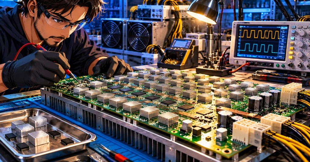
OSHRE.001 — Open-Source Hashboard Repair Engineering / Super-Fundamentals. A mining hashboard needs more than an external power connector: its ASIC cores, supporting logic and supervisory circuits must receive carefully controlled electrical power. A voltage domain is a portion of the board whose components operate across a defined electrical potential difference. Understanding the distinction between a domain’s local voltage and its voltage relative to another point on the board is foundational to safe fault analysis. This lesson builds on OSHRE.000, The Anatomy of the Hashboard, and concentrates on one teachable concept: how electrical power is organized into voltage domains.
Learning objectives
- Define voltage, electrical potential, current, local reference and voltage domain in practical terms.
- Explain the documented Antminer S9 arrangement of 63 BM1387 ASICs in 21 power domains.
- Distinguish core power from separate low-voltage logic rails and the board’s input power.
- Work through basic domain-voltage arithmetic without assuming that every board has the S9 design.
- Identify why model, revision and safety documentation are prerequisites to diagnostic measurements.
1. Voltage is a difference between two points
An electrical voltage is not a property of a single isolated point. It is the difference in electric potential between two points. If a meter shows 0.4 V between the low side and high side of an ASIC power domain, that reading describes the potential difference across the domain. It does not mean either point sits at 0.4 V relative to chassis ground. The measurement reference matters as much as the number.
This distinction is particularly important on boards with series-connected power domains. Suppose several neighboring domains each sustain roughly 0.4 V across their local supply terminals. Each may have a similar local operating voltage, yet their absolute potentials relative to one common reference step progressively upward along the series chain. Touching two locations separated by multiple domains can therefore bridge a greater potential difference than the voltage inside either local domain.
2. What makes a voltage domain?
A domain is an electrically defined group that shares an operating supply/reference arrangement. Depending on the board generation, ASICs may share a local domain in parallel while neighboring groups form a series-connected stack. Other ASIC products employ different converters, voltage regulators, voltage sensing and level-shifting schemes. A technician must never transfer a domain count or a test-point interpretation from one model to another.
A voltage domain is also different from a signal chain. A clock or command signal may pass from chip to chip and cross domain boundaries; its required signaling levels and reference relationships are separate design questions. The hashboard explainer describes the board’s broad role, while OSPCB.001 on copper layers and stackups introduces the physical copper structures that carry currents and signals.
3. The classic Antminer S9 worked example
The Antminer S9 hashboard repair reference documents 63 BM1387 mining ASICs arranged in 21 series-connected voltage domains, each with three chips. The chip population is therefore 21 × 3 = 63. It is essential to read this correctly: the three ASICs share a domain’s local core-power arrangement; they are not three independent 0.4 V drops that should be added together. The approximately 0.4 V core figure is a board- and operating-condition-specific example, not a safe universal test target.
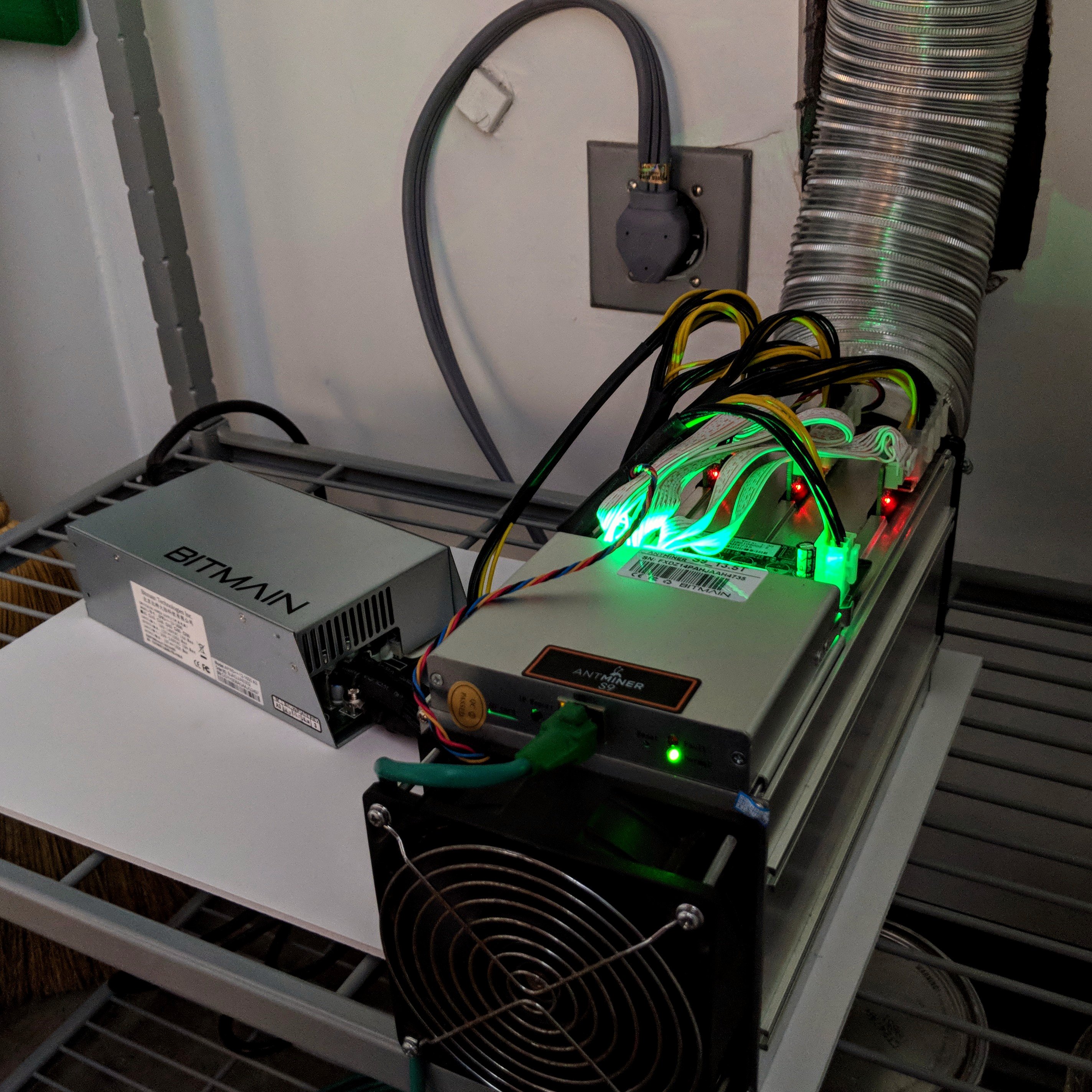
The S9 example is useful because its older service literature makes the series-domain concept explicit. Zeus Mining’s S9/S9i reference identifies 21 domains and the five familiar diagnostic signal families: CLK, CO, RI, RST and BO. Those signals are addressed only briefly here; their direction and timing warrant a separate future lesson.
4. Calculating a domain and the full stack
For a simplified, illustrative S9 model, assume each of the 21 power domains has a local core voltage of 0.40 V. The total voltage across the series stack is then 21 × 0.40 V = 8.40 V. This is an example of voltage addition across series-connected domains. It does not mean that the 12 V PSU directly delivers 0.40 V to each chip, that every chip draws an identical current, or that a real board must always measure exactly 8.40 V under every operating condition. Regulation and voltage/frequency settings affect actual values.
| Quantity | Illustrative S9 value | Meaning |
|---|---|---|
| BM1387 ASICs on one hashboard | 63 | Population documented for the reference board. |
| Chips within one voltage domain | 3 | Group sharing its local domain supply. |
| Series-connected voltage domains | 21 | Number of local domain drops added across the stack. |
| Assumed local domain difference | 0.40 V | A teaching example based on the older S9 core-voltage reference. |
| Calculated total stack difference | 8.40 V | 21 × 0.40 V; not an independent field measurement. |
Worked exercise: If a training worksheet specifies 20 equal series domains with 0.42 V across each domain, the idealized stack difference is 20 × 0.42 V = 8.40 V. Conversely, an 8.4 V stack divided into 21 equal model domains gives an average 0.4 V. Neither calculation locates a defective component; actual faults produce nonuniform changes and require proper reference points, schematics and safe test procedures.
5. Input power, step-down conversion and auxiliary rails
A hashboard does not operate all its circuitry at the same voltage. External DC input feeds the board’s power-conditioning network. A DC–DC stage can reduce and regulate the voltage applied to the ASIC core-domain stack. Separate low-dropout regulators (LDOs) and supporting circuits establish logic and clock-related supplies. On historical S9 boards, the repair documentation describes an adjustable DC–DC circuit and a 14 V boost section serving auxiliary supply arrangements. The exact distribution differs by board revision, including changes between external and integrated LDO implementation.
Capacitors stabilize supply rails by absorbing rapid current fluctuations; inductors and switching transistors are central to many switch-mode converters; feedback allows a regulator to maintain its target output despite changes in load. For a broader discussion of how miner power problems manifest, see why ASIC power supplies fail and what the miner’s control board does.
6. Video lesson — observing domain-voltage checks
The following original repair demonstration by ZEUS MINING focuses specifically on measuring domain voltages on an Antminer S9 board with a multimeter. Watch to identify how the presenter distinguishes a series-domain reading from a single-chip assumption. The video shows professional service procedures and is included for observation only; students must not reproduce energized probing without proper training and authorization.
When interpreting the demonstration, ask which two points define the measurement, what the reference board is, and whether the reported value is a local core difference, the total regulated stack, or an auxiliary rail. A label like “VDD” alone is insufficient without the schematic and measuring reference.
7. Why a defective domain can affect many chips
A damaged ASIC, local short, failed solder connection, power-regulation issue or damaged signal interface can disturb a domain or the wider chain. A missing-chip count in a fixture is only an observed symptom. It may not identify the actual failed chip or prove the entire voltage domain has lost power. The S9 service reference explicitly treats voltage imbalance, missing chips and broken signal chains as related but distinct fault categories.
| Observation | Competing explanations | Reason for caution |
|---|---|---|
| Partial ASIC count | Signal-path interruption, clock/reset problem, missing local power, faulty chip | The first undetected ASIC is not automatically the failed part. |
| No board hashrate | Input or PSU failure, board power stage, firmware/control issue, cooling protection | A zero-rate symptom may originate outside the hashboard. |
| Intermittent detection | Connector damage, supply instability, thermal fault, marginal soldering | A repeatable pattern is needed before component replacement. |
| Apparent domain imbalance | Real local power difference, wrong meter reference, adjacent domain fault | Improper reference selection can mislead and can be hazardous. |
BITMAIN’s S9 low-hashrate troubleshooting guidance also identifies PSU, controller and loose-heatsink problems as alternative causes. An engineering diagnosis uses system evidence, not a single meter value or one kernel-log message.
8. Video lesson — domain faults and missing ASIC counts
A second recorded demonstration from Salman Tech&Repair discusses domain-voltage and missing-ASIC symptoms across older hashboard families, particularly the S9. Compare the presenter’s observations with the S9 service discussion, remembering that real revisions can depart from examples in videos.
For beginners, the most important lesson is not to copy probe locations or repair actions from a different board. Instead, observe how a technician documents a symptom, compares it with a reference and tries to isolate the responsible system. This discipline carries forward into more advanced OSHRE courses.
9. Safety and revision identification
Electrical-safety boundary: ASIC miner equipment may expose mains voltage within a PSU, stored capacitor energy, very high DC currents, hot hardware and series-domain potentials that are dangerous to bridge. Only appropriately trained and authorized personnel should perform energized diagnosis, using the current manufacturer procedure, a compatible fixture, correctly rated instruments and the facility’s electrical-safety rules. This introductory course authorizes no live probing, soldering or power injection.
For an initial, de-energized intake, disconnect and isolate the unit according to the site procedure, allow the manufacturer-prescribed discharge time and have a qualified technician verify that it is safe to handle. Then record the miner model and exact PCB revision, ASIC markings, power-connector condition, visible damage and all documented test-point labels. The matching schematic and service guide must be obtained before interpreting measurements. Consider model-specific hashboard compatibility when choosing reference assemblies and fixtures.
10. Unpowered laboratory assignment
- Using a labeled, removed and verified safe board—or the historical photo above—identify the input power contacts, clusters of ASIC heatsinks, large capacitors, inductor(s), small regulators and signal connector.
- Look up the exact board-revision service document. Record the number of ASICs, known domain count and all relevant warnings. If revision details are unavailable, mark them unverified.
- Complete a paper worksheet for a fictional 21-domain series stack at 0.38 V per domain. Calculate the ideal total potential difference: 21 × 0.38 = 7.98 V.
- Create a two-column comparison of observed hardware features versus hypotheses about power design. Do not infer hidden copper routing from top-side appearance alone.
- Explain in three sentences why a 0.4 V local difference and an 8.4 V board-stack difference can both be valid without contradiction.
11. Knowledge check
- Is voltage measured at one isolated point, or between two points?
- How many BM1387 ASICs and voltage domains are documented on the standard S9 board used in this lesson?
- Does 21 × 0.40 V = 8.40 V mean each of the 63 chips independently receives 8.40 V?
- What is the conceptual difference between a core supply domain and an auxiliary 1.8 V logic rail?
- Name two non-chip causes that may produce zero hashrate or missing board detection.
- Why is copying a multimeter probe location from another hashboard model unsafe?
Answer key: (1) Between two points. (2) 63 ASICs arranged in 21 domains of three. (3) No; it models the sum of local domain potential differences in a series stack. (4) Core domains supply mining circuitry while auxiliary rails power other functional blocks or interfaces. (5) Examples: faulty PSU, loose power connection, control-board issue, signal interruption or thermal shutdown. (6) References, layouts, domains and hazards may differ; bridging adjacent potentials can damage hardware or injure personnel.
12. Primary references and continued learning
The foundational reference is the Antminer S9 hashboard maintenance documentation, supported by Zeus Mining’s S9/S9i board overview and BITMAIN’s manufacturer troubleshooting guidance. For PCB fundamentals, continue through OSPCB.002 on pads, vias and through-holes. OSHRE.002 will isolate one neighboring concept, such as chip-chain signals and clock distribution, rather than combining every repair procedure into this foundation lesson.
BitcoinVersus.Tech — Independent, open technical education.
BitcoinVersus.Tech Editor’s Note: This lesson is intended for introductory engineering education, not as authorization for energized repair. Support independent technical learning with a contribution of 5,000 sats. Scan the original donation QR code below with a compatible Bitcoin wallet, and confirm that the receiving address is 3C9o19EH5HSiwEPyCTmEKzxhNCbo2X6TTb before sending.

Open the QR code on another screen and scan it with your Bitcoin wallet. BitcoinVersus.tech is not a financial advisor. This media platform reports on financial subjects purely for informational purposes.


Leave a Reply