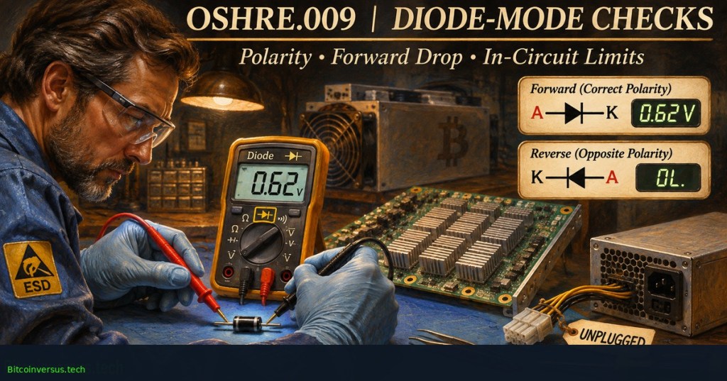
OSHRE.009 examines what a multimeter’s diode-test function can reveal about an isolated electronic component—and why the same reading across a populated Bitcoin ASIC hashboard requires caution. Unlike continuity mode, which usually reports whether a conducting path meets a meter threshold, diode mode applies a small test current and displays the resulting voltage drop. The measurement supports troubleshooting but does not identify a failed ASIC by itself. The preceding OSHRE.008 explains continuity, resistance and low-resistance parallel paths.
Fluke Corporation, October 22, 2024. Manufacturer demonstration using the Fluke 87V multimeter to test diodes, capacitors and resistors, including the need to interpret results carefully. Credit: Fluke Corporation / YouTube.
Polarity defines a meaningful diode reading
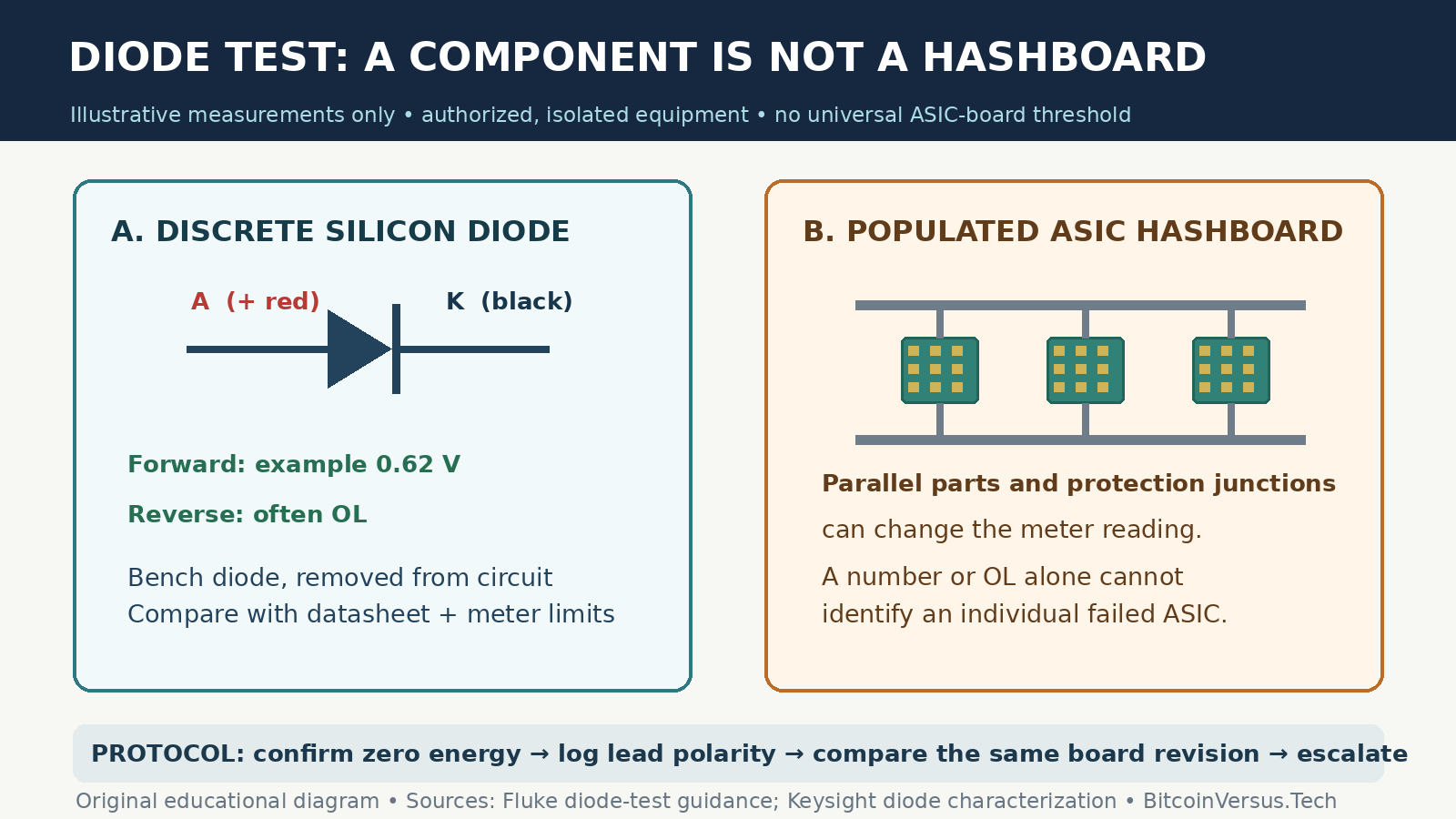
For an isolated conventional silicon diode, the positive red lead on the anode and the negative black lead on the cathode place the junction in forward bias. Fluke’s diode-testing guide describes typical forward indications around 0.5–0.8 volts for common silicon diodes. Reversing the probes commonly produces OL, indicating no conduction within the meter’s measurement conditions. Different diode chemistries, temperature, instrument test currents and meter voltage limits can produce other results.
A display reading is a voltage under the instrument’s test conditions—not an ohmic resistance measurement or proof that every connected semiconductor works. Keysight’s diode-characterization guidance distinguishes a single meter test from a full current-voltage curve, where forward and reverse behavior are assessed across multiple operating points.
Why hashboards complicate the interpretation
A hashboard contains ASICs, protection components, capacitors and interconnected supply and signal paths. The meter’s injected current may encounter more than one component, so a reading between accessible points can include multiple junctions or alternate paths. An apparent forward drop does not necessarily belong to the suspected chip. Likewise, OL can mean that the specific applied test voltage cannot establish conduction—not necessarily that an ASIC is open-circuit.
The OSHRE.001 voltage-domain lesson explains board power organization. OSHRE.002 distinguishes clock, response and reset signaling from power faults. Neither layer is diagnosed conclusively by a lone diode-mode result.
Record reproducible evidence, not a verdict
Only trained, authorized technicians should inspect exposed miner electronics. Follow model-specific shutdown and lockout requirements, disconnect every power source and verify absence of hazardous energy with an appropriately rated instrument. Residual capacitor energy requires approved discharge and re-verification; never use diode mode on an energized circuit or as a substitute for absence-of-voltage testing. ESD precautions and contamination inspection are covered in OSHRE.007.
The Tech Circuit, “#68 – Testing Diodes with a Multimeter,” October 15, 2023. Educational comparison of in-circuit and out-of-circuit tests, conventional and Schottky diodes, and Fluke meter behavior. Credit: The Tech Circuit / YouTube.
In an approved, deenergized workshop assessment, log the exact board revision, meter model, measurement points and lead orientation. Compare each recorded reading with the same points on a known-good equivalent and any manufacturer-published reference. If results conflict, escalate to documented component isolation or controlled fixture testing rather than guessing from a familiar voltage. The OSHRE.006 inspection lesson describes how visual evidence can complement electrical findings without establishing a fault alone.
Technical conclusion: Diode mode is a valuable way to characterize semiconductor junctions under limited test conditions. On a complex ASIC assembly, probe polarity, parallel paths and comparison baselines determine whether a measurement is useful; neither an apparently normal reading nor an OL display certifies board health.
Editor’s Note: Primary testing principles were reviewed against Fluke and Keysight documentation. Videos were identified through the publishers’ public YouTube listings; real playback can differ from successful WordPress iframe rendering. The 1200 × 630 oil-painted cover is an original conceptual illustration with the Bitcoinversus.tech watermark, and the in-story schematic contains an illustrative diode example rather than a manufacturer-defined hashboard limit. No energized hardware or production hashboard was tested.

BitcoinVersus.Tech is volunteer-run and publishes independent technical education. An optional 5,000-satoshi donation supports ongoing research. Scan the original QR from a second screen using a compatible Bitcoin wallet; on the same phone, use a wallet that can import a saved QR image when supported. Independently verify recipient 3C9o19EH5HSiwEPyCTmEKzxhNCbo2X6TTb and the amount before sending. Bitcoin transactions are generally irreversible.
We volunteer daily to ensure the information on BitcoinVersus.Tech is Verifiably True. Coverage is for education and information, not authorization to repair energized electrical hardware, certified engineering advice, financial advice or investment advice.


Leave a Reply