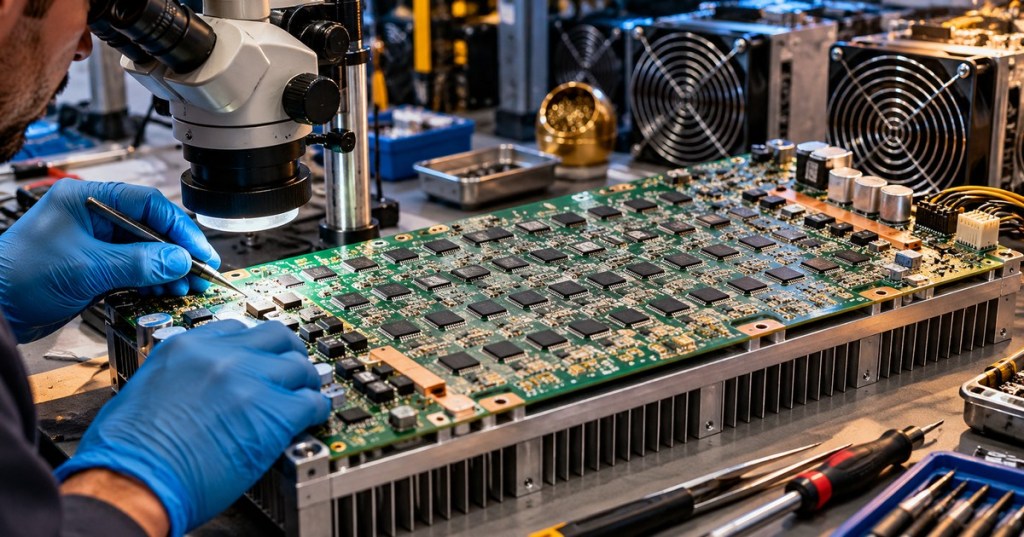
OSHRE.000 — Open-Source Hashboard Repair Engineering / Super-Fundamentals. A hashboard is a specialized printed-circuit assembly carrying the ASICs that execute Bitcoin mining calculations. It is not the miner’s control board, power supply or network interface. This opening lesson surveys how hashboards developed, what sits on them, why different generations cannot simply be interchanged, and how repair engineers recognize the fundamental electrical and thermal systems before attempting fault isolation. For a shorter introduction, see what a hashboard is; this course begins the engineering-level treatment.
Learning objectives
- Trace the historical move from CPU/GPU/FPGA mining to dedicated ASIC circuit boards.
- Identify the major physical parts of a hashboard and explain its power, data and thermal interfaces.
- Compare documented chip populations and architecture across selected Antminer, Avalon, WhatsMiner and open-hardware designs.
- Separate safe identification and observation from energized troubleshooting and component rework.
- Explain how modern cooling and silicon efficiency may change future hashboard design.
1. From software mining to dedicated hardware
Bitcoin launched in 2009 with proof-of-work computation running on general-purpose CPUs. GPUs and subsequently FPGAs brought parallelism and configurable logic, but ASICs eventually concentrated the SHA-256 computation in purpose-built silicon. The shift is outlined in Bitcoin mining’s CPU-to-ASIC history. In 2013, Canaan’s Avalon operation shipped pioneering dedicated ASIC-based Bitcoin mining machines. The enduring architecture was already visible: repeated mining chips on substantial circuit boards, power distribution and aggressive heat removal.
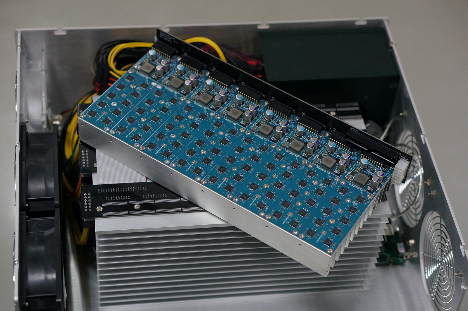
The 2013 Avalon photograph shows a blue PCB mounted above a sizable aluminum heatsink with cooling hardware and power wiring close by. Modern units have moved to smaller semiconductor processes, higher chip density and more specialized cooling, but the board-level engineering problems—clean voltage delivery, reliable signal propagation, thermal contact and repairability—remain recognizable.
2. What exactly is on a hashboard?
The board itself is a multilayer printed circuit board (PCB) made of insulating laminate and patterned copper. It carries electrical connections, surface-mounted components, mounting holes, thermal interfaces, identifiers and sometimes controller-facing supervisory electronics. On a typical industrial air-cooled hashboard, a technician should be able to identify the following systems without applying power.
| Component or feature | Engineering purpose |
|---|---|
| SHA-256 mining ASICs | Perform repeated double-SHA-256 mining calculations on work assigned by the controller. |
| Power contacts, busbars and copper planes | Deliver substantial DC current to chips and voltage-regulation circuits. |
| Voltage domains and regulation | Distribute or convert power to levels required by the ASIC core and I/O circuitry. |
| Signal connectors and conductors | Carry clock, command, reset, result and other control signals, depending on board family. |
| Oscillators, sensors and supervisory ICs | Support timing, temperature monitoring, board identification and local supervision. |
| Capacitors, resistors, inductors, MOSFETs | Filter and switch power, bias logic, shape signals and support regulation. |
| Heatsinks, cold plates and thermal interfaces | Conduct chip heat toward air or liquid-based heat-removal systems. |
| Silkscreen, revision marks and test points | Help identify the exact board revision, component locations and diagnostic access points. |
The control board manages firmware, network communications and work distribution. The power supply converts facility power into the required miner input. The hashboard converts its share of electrical power into intensive repeated hashing activity, with almost all consumed electricity ultimately becoming heat.
3. ASIC chips and their packages
Each mining ASIC is a semiconductor package mounted to the PCB. Its internal circuitry processes nonces and related work information according to the chip’s design; exact internal control protocols are often proprietary. Do not confuse the visible package with the tiny silicon die inside it. Package dimensions, pin arrangement, solder pads and heat paths can differ substantially between BM1387, BM1398, BM1366, BM1370 and other generations. A technician must match the specific chip and board revision before sourcing replacements.
A chip part number is not a universal compatibility promise. For example, the open-source Bitaxe Gamma project documents a BM1370 chip sourced from the S21 Pro design and notes that its footprint and pinout differ from earlier BM-series chips. Physical fit, electrical levels, firmware support and thermal assembly must all match; see why hashboards are not universally interchangeable.
The following technical repair demonstration shows the physical BM1397 package removal and board pad preparation on an Antminer T17 hashboard. It illustrates professional chip-level handling—not a substitute for training, safe isolation or a model-specific service procedure.
4. Power architecture and voltage domains
A voltage domain is a portion of a board operating at a defined potential relative to neighboring domains. Some hashboard families stack domains in series; others use different regulator and level-shifting arrangements. It is unsafe to assume every ground-looking point has the same potential. Series-domain designs may expose many different reference voltages across a board, even when each chip runs at a small local voltage.
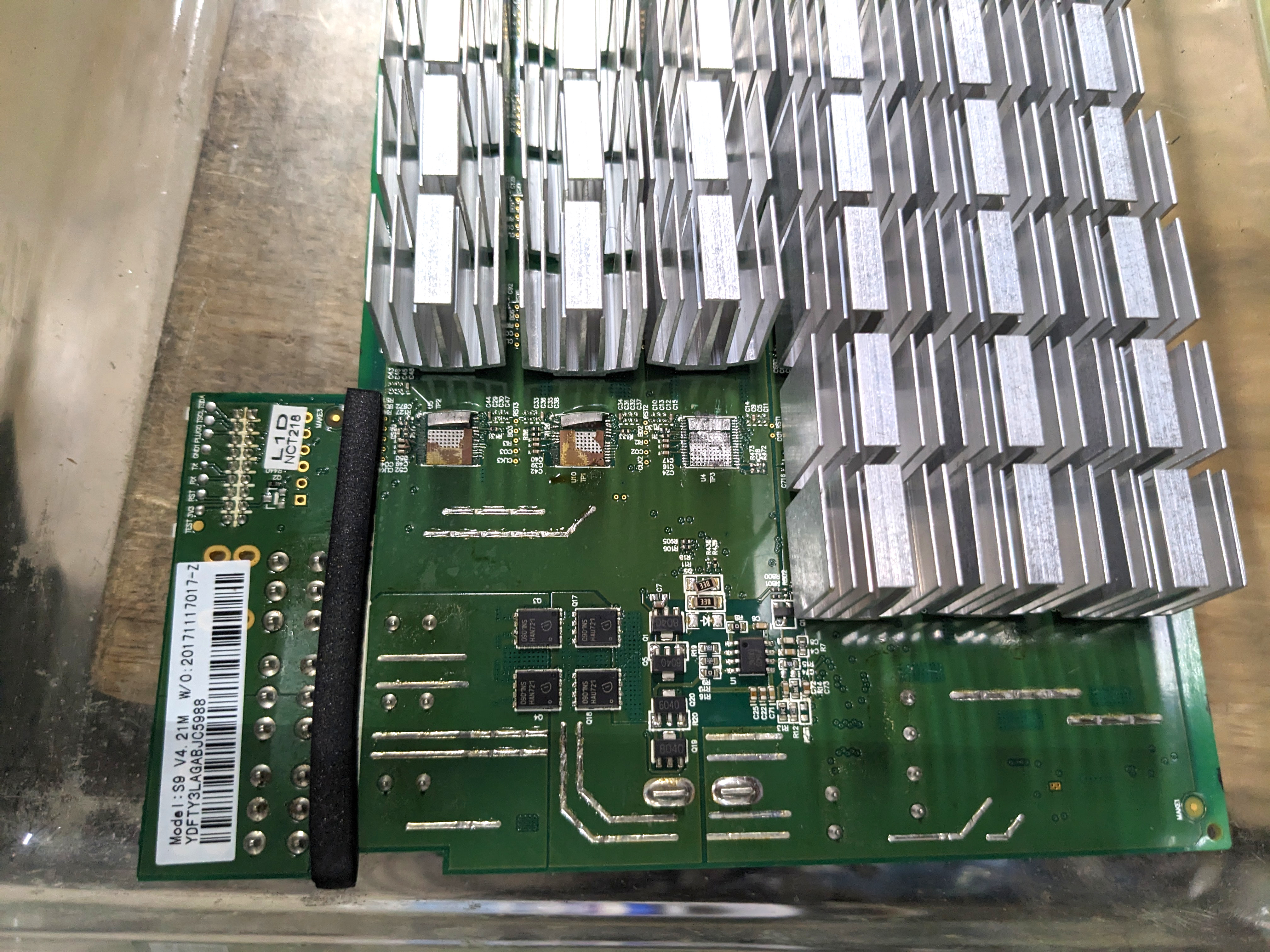
A documented Antminer S9 hashboard contains 63 BM1387 chips arranged as 21 voltage domains of three chips each. Later S19 Pro BM1398 repair references document a different grouping: 114 chips in 38 domains of three for that specific board family. These are architecture examples, not universal specifications for every S9/S19-related revision.
The capacitor bank reduces power ripple; switching devices and regulators establish supply conditions; conductors must withstand large currents without excessive heating. A badly seated connector, damaged MOSFET, failed regulator or shorted ASIC can disable a board. Yet a machine that boots and shows an IP address does not prove its hashboards are healthy: related power supply failures can mimic a board fault.
5. Clock, command and result paths
The host assigns work; the board distributes it among ASICs; chips report candidate results back to the controller. The precise chip-chain signal names depend on generation, but technicians often encounter CLK (clock), CO/CI (command out/in), RI/RO (response input/output), RST (reset) and BO/BI (busy/status direction) labels in Antminer repair materials. These labels are family-dependent, so use the correct manufacturer schematic or repair guide.
A broken signal path, open solder connection, unstable oscillator, failed level shifter or nonresponding ASIC may cause a board to enumerate only a partial chain. A log stating that fewer chips were found identifies a symptom, not the failed component by itself. Bitmain’s S9 low-hashrate support guide likewise distinguishes board, PSU, control board and cooling problems.
6. Board families, models and documented specifications
The most useful repair comparison is a named board revision, not just the marketing name on the outer chassis. The examples below draw from model-specific service documents and project repositories; chip counts in unverified revisions must be rechecked against physical board markings and official parts documentation. Whole-miner TH/s and wall power must not be mistaken for per-board or per-chip measured values.
| Design | Verified or documented characteristics | Important repair distinction |
|---|---|---|
| Antminer S9 (2016 generation) | 63 BM1387 chips per board, 21 groups of three; commonly three boards per machine. | Older air-cooled series-domain architecture; exact board version matters. |
| Antminer S19 Pro BM1398 board | 114 chips per board, grouped as 38 × 3 in a documented repair variant. | Different power-conditioning and signal architecture from S9; do not mix fixtures or chip types. |
| Antminer S21 Pro | Manufacturer nominal 234 TH/s, 3,510 W, 15 J/TH at 25°C inlet; Bitaxe Gamma project reports 3 × 65 BM1370 chips. | Nominal hashrate and power are whole-miner specifications; chip count is project-reported. |
| WhatsMiner M30S series | MicroBT-specific mining ASICs and proprietary board/control ecosystem. | Not a BM-series Antminer design; component and fixture interchange should not be assumed. |
| AvalonMiner 1246 | Service reference reports A3210 chips, 38 per board across three boards. | Canaan board layout, firmware and control interfaces differ from Bitmain and MicroBT. |
| Bitaxe Ultra / Gamma open hardware | Small single-ASIC boards: BM1366 Ultra and BM1370 Gamma, with published PCB design files. | A teaching-friendly board architecture, not a drop-in industrial hashboard replacement. |
For a numeric example, Bitmain lists the S21 Pro at 3,510 watts and 234 TH/s. Dividing wall power by hashrate gives 3,510 ÷ 234 = 15 J/TH, the nominal machine-level efficiency. Dividing 234 TH/s by the project-reported 195 ASICs gives about 1.2 TH/s per chip as a simple uniform-share estimate, not a direct measured chip benchmark.
7. Thermal systems and mechanical construction
Mining ASICs produce heat continuously. Industrial air-cooled boards normally use heatsinks in a forced airflow path. Hydro-cooled designs transfer heat to liquid through compatible cold plates or integrated thermal assemblies. Immersion-cooled assemblies operate inside an engineered dielectric fluid system. These variants can differ in PCB geometry, coatings, connectors, allowable materials, sensor placement and safe servicing procedures.
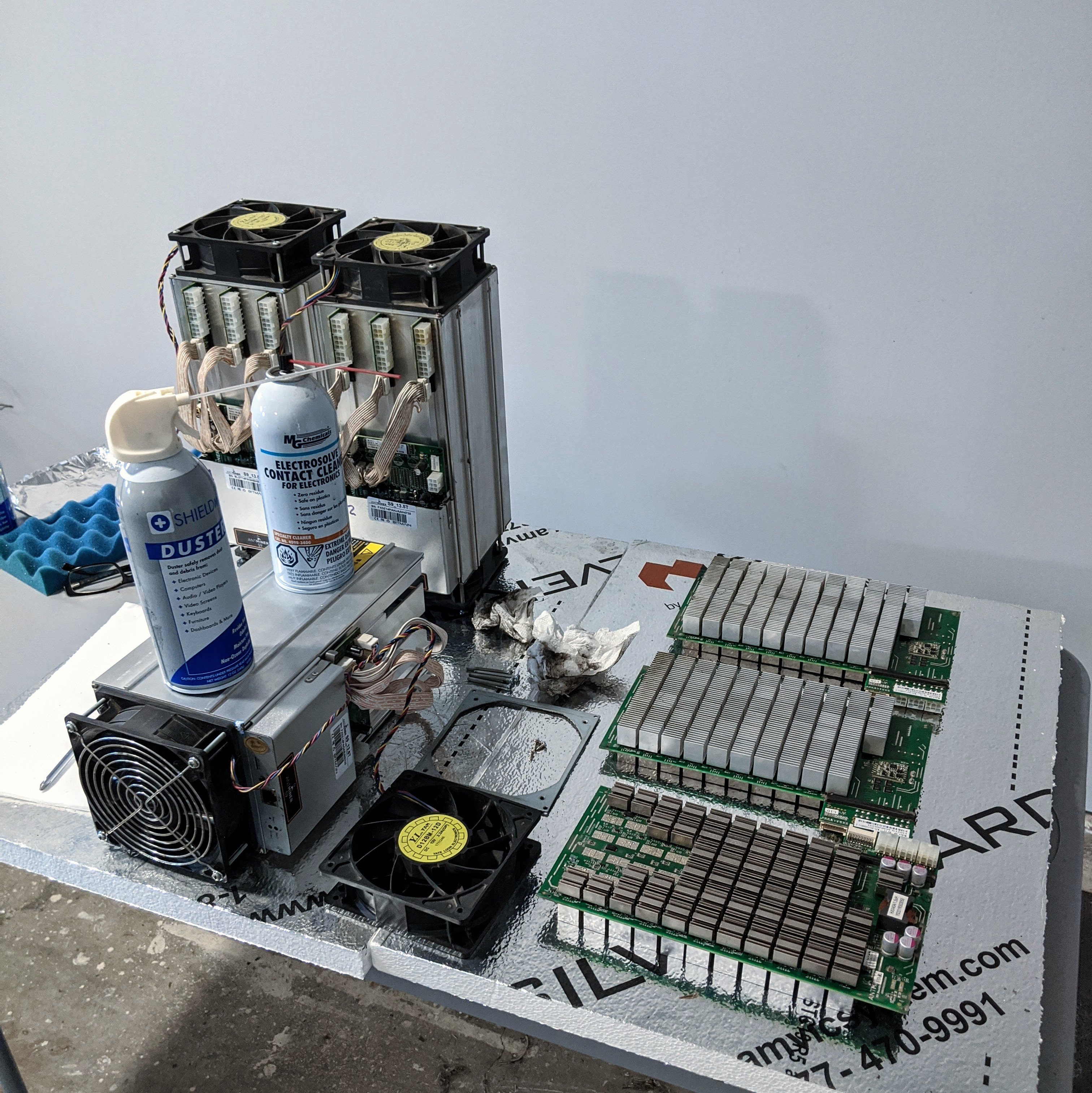
Heat-transfer materials and mechanical pressure are part of the electrical design’s reliability. Loose heatsinks, failed thermal compound, warped boards and obstructed airflow can lead to throttling, errors or failure. A board may be electrically intact yet unable to meet its nominal hashrate under thermal load. For context on actual chip-level service operations, see GoMining’s ASIC repair coverage.
8. Safe identification and introductory fault isolation
Safety first: A miner’s AC input, stored PSU energy, high-current DC paths and hot components can injure technicians or damage equipment. Never open an energized miner or probe live power domains unless trained and authorized under a documented electrical-safety procedure. Disconnect power, apply the facility’s isolation/lockout procedure, wait the manufacturer-specified discharge period, and verify the safe state with appropriately rated instruments. Specialized chip-level work belongs at a qualified electronics rework station.
At the foundation level, safe unpowered inspection begins with reading the miner label and PCB revision; photographing connectors before separation; recording logs and board inventory from the controller; observing discoloration, cracked solder, corrosion, contamination or missing heatsinks; and confirming that replacement parts match the exact board family. An experienced repair engineer then uses model-specific documentation, isolated test fixtures and rated measurement equipment to distinguish power, clock, signal, sensor and ASIC faults.
| Observed symptom | Possible fault categories — not a diagnosis |
|---|---|
| Control interface works, one board absent | Board power connection, controller cable, PSU output, board supervisor or ASIC chain fault. |
| Board detects only part of chip chain | Clock/command/return signal path, damaged chip or solder joint, or failed local power domain. |
| All boards report low hashrate | Power limits, firmware settings, pool workload, inlet temperature, airflow or system-wide PSU behavior. |
| Sudden temperature shutdown | Fan or pump issue, heatsink contact, sensor fault, thermal interface, blocked cooling path. |
| Intermittent hash errors | Marginal supply regulation, signal integrity, overheating, chip degradation or unstable tuning. |
Good fault isolation avoids replacing chips simply because a log shows “missing ASIC.” Preserve the baseline data, verify the test fixture, compare with a known-good assembly of the same revision, document each measurement and rerun the same acceptance tests after repair. Manufacturer warranty and service terms may restrict component-level interventions.
A dedicated Bitmain hashboard test fixture helps trained repair technicians interpret ASIC chain responses before choosing a repair. In this recorded demonstration, Antminer Repair examines test-fixture serial output and shows why a reported bad chip alone may not establish the true diagnosis.
9. The future of hashboard engineering
Future hashboards may integrate denser power distribution, more advanced semiconductor packages, refined voltage control, additional telemetry, liquid-cooling integration and increasingly modular service arrangements. These are engineering directions, not guarantees for any specific release. The mass and computational-density discussion illustrates why board geometry and cooling are becoming as strategically important as raw chip count.
Energy efficiency should be evaluated using clearly defined boundaries: chip test, hashboard input, complete miner wall plug or whole site. A 6–7 J/TH laboratory chip claim is not automatically the performance of a production miner. Our coverage of SEAL chip generations and the 1 J/TH timeline separates tested silicon, operational measurements and forecasts. Repair engineering will increasingly demand both semiconductor literacy and thermal-fluid/electrical-system competence.
10. Laboratory exercise: inspect without energizing
- Select a removed, de-energized board or use the credited reference photographs above. Record the model family, silkscreen revision, visible chip population and type of cooling interface.
- Identify the PCB laminate, ASIC packages, visible power contacts, large passive components, signal connector and diagnostic test-point labels without touching energized circuitry.
- Locate the matching service documentation. Record which component names and voltages are verified for this exact revision and which are unknown.
- Compare the board with one other generation. Note three differences in chip count, power design, physical geometry, connector layout or thermal hardware.
- Write a short intake note distinguishing observable facts from hypotheses; do not diagnose or rework a device on appearance alone.
11. Knowledge check
- What is the functional difference between the control board and hashboard?
- How many BM1387 chips and voltage domains are documented for one standard S9 hashboard?
- Why must a technician identify the exact board revision before replacing an ASIC?
- Why is 15 J/TH on the S21 Pro specification a whole-miner figure rather than an isolated chip measurement?
- Name two board-level mechanisms that can cause partial ASIC enumeration, and two safety checks required before inspection.
Answer key: (1) The controller manages work and networking; hashboards perform hashing. (2) 63 chips and 21 domains. (3) Package, pinout, electrical compatibility and mechanical details differ. (4) It is calculated from 3,510 W of stated wall power divided by 234 TH/s of stated machine hashrate. (5) Examples include chain signal faults and failed power domains; isolate energy and verify a safe de-energized condition before touching hardware.
References and next study
Primary and manufacturer references include Canaan’s ASIC history, Bitmain’s S9 troubleshooting guide, Bitmain’s S21 Pro specification, MicroBT’s spare-parts compatibility guidance and the Bitaxe Gamma hardware repository. Selected board-level counts are additionally attributed to S9 service literature and model-specific repair references; verify against the actual revision before repairs. Subsequent OSHRE lessons will address voltage domains, signal-chain anatomy, thermal interfaces, test fixtures and non-destructive diagnostics as separate concepts.
BitcoinVersus.Tech — Independent educational reporting and open-source engineering instruction.
BitcoinVersus.Tech Editor’s Note: This introductory lesson teaches equipment identification and conceptual fault categories; it does not authorize energized repairs or replace manufacturer safety procedures. If the course helps you learn, support independent engineering education with a 5,000-satoshi contribution. Scan the original QR code below with a compatible Bitcoin wallet, or verify the receiving address: 3C9o19EH5HSiwEPyCTmEKzxhNCbo2X6TTb.

Open the QR image on another screen and scan it with your Bitcoin wallet. Verify the receiving address before sending. BitcoinVersus.tech is not a financial advisor. This media platform reports on financial subjects purely for informational purposes.


Leave a Reply