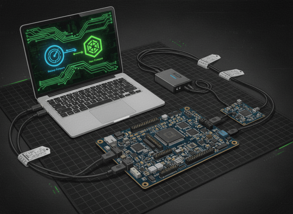
Firmware service is controlled change on hardware that can become unusable if the wrong image, wrong target, interrupted write, incompatible configuration, or failed recovery path is handled badly.
This is OSFTC.001, the first lesson in the Open Source Firmware Technician Certification track. It establishes the field workflow for identifying firmware, backing up what matters, validating an image, entering the correct boot or recovery mode, flashing through the right interface, preserving rollback options, collecting evidence, and proving the device works after the change.
The safe firmware workflow
identify exact hardware → record current version → back up configuration/image if supported → obtain approved image → verify integrity and compatibility → establish recovery path → enter correct programming mode → flash without interruption → reboot → validate hardware functions → compare logs/telemetry → document result → retain rollback evidence
1. What firmware is
Firmware is software stored in nonvolatile memory that controls hardware at a low level. Depending on the device, it may initialize processors, configure peripherals, expose network or serial interfaces, manage sensors and power states, enforce security policy, or launch higher-level software.
Firmware can live in internal MCU flash, external NOR/NAND flash, EEPROM, eMMC, SPI flash, or another nonvolatile storage device. A single product may contain several independent firmware images for a main processor, management controller, FPGA, power controller, network device, or peripheral.
The Armv8-M architecture lesson provides useful background for understanding the processor side of many embedded devices.
2. Never start with the file—start with the target
Before flashing anything, identify the exact target:
- manufacturer and model;
- PCB or hardware revision;
- processor or controller part number;
- bootloader version if exposed;
- current firmware version/build;
- memory size or flash layout where relevant;
- region, feature, or hardware variant;
- power requirements;
- supported programming/recovery interface.
A file that is valid firmware for one board revision can still be destructive on another. The warning pattern is familiar in mining hardware too: firmware compatibility and installation restrictions can change across vendor releases and hardware generations.
3. Record the current state before changing it
Capture enough evidence to reconstruct what existed before the change:
- current firmware version and build identifier;
- bootloader version;
- device serial number or asset identity;
- configuration export;
- network settings;
- calibration or tuning data if applicable;
- logs and health state;
- screenshots or command output showing normal operation;
- backup of the existing image if the platform and authorization allow it.
This is the firmware equivalent of creating a known-good baseline. The AxeOS firmware guide provides a practical mining-device example of how firmware, configuration, and hardware behavior stay tightly coupled.
4. Verify the image before flashing
An approved firmware image should come from a trusted release location or controlled internal repository. Verify the filename, version, target family, release notes, and integrity information before starting the write.
A checksum or cryptographic hash such as SHA-256 can detect accidental corruption when compared against a trusted published value. Integrity is not the same as authenticity. A matching hash proves only that the bytes match the trusted reference hash. Digital signatures and a trusted signing chain are stronger authenticity controls.
Video 1: Boot modes, system bootloader, and SWD
5. Understand the boot chain
The boot chain is the sequence that takes the device from reset to running application firmware. A simplified embedded path may look like:
reset → boot-mode selection → ROM/system bootloader or primary bootloader → validate/select application image → initialize runtime → application starts
Not every platform uses the same structure. On many STM32 devices, for example, ST provides a factory system-memory bootloader that can accept code through selected interfaces such as USART, USB, CAN, I²C, or SPI depending on the specific MCU. ST documents these device-specific details in AN2606: STM32 system memory boot mode.
The technician rule is: do not assume the recovery method from a similar chip applies to this chip. Read the target’s actual documentation.
6. Main flash, system memory, and recovery modes
A microcontroller may boot from its normal application flash, a factory bootloader in ROM/system memory, SRAM, or another mapped location depending on option bytes, boot pins, straps, fuses, and device family.
For STM32 as one example, ST explains that boot configuration is resolved at reset and that the system bootloader is stored in internal system memory programmed at production. The exact behavior varies by family and device. See ST’s STM32 boot-process reference.
7. Serial console and UART: an early recovery window
A UART or serial console can expose boot messages before network services start. It may reveal:
- bootloader banner and version;
- memory initialization;
- flash-detection errors;
- kernel or RTOS startup;
- watchdog resets;
- failed image validation;
- filesystem or configuration problems;
- recovery prompts.
Technicians must confirm voltage levels before connecting. A 3.3 V TTL UART is not the same electrical interface as classic RS-232. Incorrect voltage or pinout can damage hardware.
8. SWD and JTAG: programming plus low-level visibility
SWD and JTAG are common hardware debug/programming interfaces. Depending on the target and security configuration, they can allow tools to halt the processor, inspect memory/registers, erase or program flash, set breakpoints, and recover a board that no longer boots normally.
These interfaces are powerful enough to make a bad situation worse. Confirm target voltage, pinout, ground reference, reset behavior, interface selection, and device identity before issuing erase/program commands.
Video 2: SWD, ST-Link, flashing, and debugging
9. Safe flashing is mostly about controlling failure modes
Before pressing Program, eliminate preventable failures:
- stable power source;
- known-good cable and programmer;
- correct target selection;
- correct image;
- verified bootloader/recovery path;
- configuration backup;
- no pending power shutdown or maintenance conflict;
- laptop power secured where applicable;
- no other tool simultaneously accessing the target;
- documented rollback procedure.
The Bitaxe/NerdAxe web-flasher story provides a real-world example of reducing technician friction by standardizing the flashing path.
10. Erase, program, verify
Many flashing workflows reduce to three core operations:
- Erase the required flash region.
- Program the new image into the correct address range.
- Verify the programmed contents against the source image or tool’s verification method.
Do not use a full-chip erase when the procedure only requires a region erase unless the vendor procedure explicitly calls for it. Full erase can destroy calibration, keys, device identity, factory data, option bytes, or configuration stored outside the application image.
11. Flash addresses matter
A valid binary written to the wrong address is still wrong. Technicians should know whether the image format carries address information:
- .bin files are often raw bytes and may require the operator to provide the start address.
- .hex and .elf files can contain address/section information, depending on the tool and workflow.
Follow the vendor’s exact procedure. Never guess the flash base address from a different board.
12. Backup and rollback are part of the flash plan
A firmware change is not complete until failure and rollback behavior are understood.
- Can the previous image be restored?
- Can configuration be imported separately?
- Is there an A/B image scheme?
- Does the bootloader automatically fall back?
- Is there a recovery button, jumper, serial command, or ROM bootloader?
- Does secure boot prevent older images from loading?
- Will rollback cross a bootloader or data-format compatibility boundary?
The NMAxe recovery story shows why recovery behavior deserves first-class attention rather than being treated as an afterthought.
13. Configuration is not always firmware
Keep firmware image, bootloader, calibration data, keys, and user configuration conceptually separate. An upgrade may preserve some of them, migrate some, or erase some.
Do not assume a successful flash preserves network settings, pool credentials, tuning values, certificates, or calibration. Read the release notes and back up independently when supported.
14. Post-flash validation
“Programming completed successfully” only proves the programmer completed its task. It does not prove the device works.
After reboot, validate:
- reported firmware version;
- bootloader and boot reason;
- serial/console startup log;
- network link and management access;
- sensors and telemetry;
- fans, pumps, relays, or actuators where applicable;
- clock/time state;
- configuration persistence;
- error counters;
- normal workload;
- reboot behavior;
- recovery path if required by the test plan.
For mining hardware, the same discipline appears in first-boot-to-first-share validation: a device is not truly restored until the intended workload is functioning.
Video 3: What JTAG and SWD are actually doing
15. Common ways technicians brick devices
- flashing firmware for the wrong hardware revision;
- losing power during an unprotected bootloader update;
- erasing factory/calibration regions;
- writing a raw binary at the wrong address;
- changing option bytes or fuses without understanding the consequences;
- disabling the only available debug/recovery interface;
- interrupting bootloader or partition migration;
- ignoring secure-boot/anti-rollback rules;
- restoring an incompatible old configuration after a schema change;
- assuming network recovery will work after the device loses its network configuration.
16. Firmware technician field checklist
- Identify the exact hardware and revision.
- Record current firmware and bootloader versions.
- Export configuration and calibration data where supported.
- Save current logs/telemetry.
- Confirm the approved target firmware.
- Read release notes and compatibility warnings.
- Verify hash/signature when provided.
- Confirm stable power.
- Confirm the programming interface and voltage.
- Confirm recovery mode before erasing anything.
- Flash using the documented address and method.
- Verify the written image.
- Reboot and watch startup logs.
- Verify version, networking, sensors, and workload.
- Confirm rollback or recovery remains possible.
- Document the final state and evidence.
Practice exercise
A technician receives a control board labeled revision B. It currently reports firmware 1.4.2. A ticket specifies an upgrade to 1.7.0, but the download folder contains builds for revisions A, B, and C. The device has Ethernet, a USB service port, UART pads, and an SWD header.
- Which firmware file should be selected?
- What evidence should be captured before the upgrade?
- How can image integrity be verified?
- Which recovery interfaces exist if normal boot fails?
- What electrical/interface information must be known before attaching a USB-to-UART adapter?
- What should be validated after the flash?
- What information should be recorded in the ticket?
Knowledge check
1. What is the first thing to identify before flashing?
The exact hardware target and revision.
2. Does a matching checksum prove firmware is authentic?
Not by itself. It proves byte integrity relative to the trusted checksum; authenticity requires a trusted source or signature chain.
3. Why is a bootloader important to a technician?
It may provide the path used to load, select, validate, or recover application firmware.
4. What is the difference between a successful flash and a successful repair?
A flash is successful when bytes were programmed correctly; the repair is successful only when the device boots and performs its required functions.
5. Why should technicians care about SWD/JTAG?
They can provide low-level programming and debug access when normal software paths fail.
6. Why avoid unnecessary full-chip erase?
It may destroy configuration, keys, calibration, identity, option bytes, or other factory data outside the application image.
Key takeaway
Firmware technicians protect recoverability. Identify the exact target, preserve the current state, verify the new image, understand the boot path, control power and interfaces, flash carefully, validate the real workload, and leave enough evidence that another technician can recover or reproduce the result.
Safety and service note: Firmware programming can permanently change security state, option bytes, calibration, keys, or boot behavior. Use the manufacturer’s procedure, approved tools, ESD controls, correct interface voltages, and site change-management requirements.
BitcoinVersus.Tech
Advertisement
Editor’s Note:
We volunteer daily to ensure the credibility of the information on this platform is Verifiably True. If you would like to support our research initiatives, please donate here: 3C9o19EH5HSiwEPyCTmEKzxhNCbo2X6TTb
BitcoinVersus.tech is not a financial advisor. This media platform reports on financial subjects purely for informational purposes.


Leave a Reply