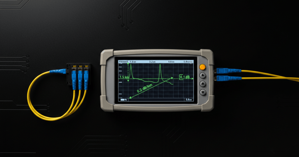
An optical time-domain reflectometer, or OTDR, sends short optical pulses into a fiber and measures returned Rayleigh backscatter and reflections over time. That lets a technician estimate distance, attenuation, event loss, reflectance, and the location of breaks, connectors, splices, bends, or other faults along the link.
Prior lessons
- OSFOTC.001: Fiber Optic Safety, Handling, Inspection, and Cleaning Basics
- OSFOTC.002: Optical Power Meter Basics — dBm, Wavelength, Reference Levels, and Receive Power
- OSDCTC.003: Structured Cabling and Patch Panels
What an OTDR actually measures
The OTDR does not directly measure end-to-end received power like the optical power meter from OSFOTC.002. Instead, it launches a pulse and watches how much light returns as a function of time. The instrument converts that round-trip time into distance using the fiber’s group index, conceptually following distance ≈ ct/(2n), where the factor of two accounts for the pulse traveling out and the backscatter or reflection returning to the tester.
Launch and receive fibers
A launch fiber places known fiber length between the OTDR port and the first connector under test, while a receive fiber extends the link beyond the far-end connector. These fibers let the instrument characterize loss and reflectance at both ends of the installed link instead of burying those connectors inside the OTDR’s near-end or far-end measurement limitations.
OTDR setup: wavelength, range, pulse width, and acquisition time
Before testing, the technician selects or confirms wavelength, distance range, pulse width, acquisition duration, index-of-refraction/group-index settings, and launch-cable handling. Automatic modes can be useful, but a technician should understand each parameter because the wrong setup can hide nearby events, increase noise, or make the trace harder to interpret.
Range setting
The distance range should extend beyond the expected fiber length so the complete link and fiber end are visible without wasting excessive trace resolution on empty distance. A range that is too short can truncate the link; a range that is unnecessarily long can make event placement and display resolution less useful for short links.
Pulse width
Short pulses improve spatial resolution and help separate closely spaced events, while longer pulses place more optical energy into the fiber and improve dynamic range for longer or higher-loss links. The tradeoff is fundamental: increasing pulse width can make distant events easier to see but can also widen dead zones and merge nearby events into one apparent feature.
Wavelength selection
Singlemode OTDR testing commonly uses wavelengths such as 1310 nm and 1550 nm, while multimode testing commonly uses 850 nm and 1300 nm when supported by the instrument and acceptance procedure. Testing at more than one wavelength can help reveal wavelength-sensitive bending or loss behavior that may not be obvious from a single trace.
Reading the trace
An OTDR trace normally slopes downward because backscatter decreases as the pulse experiences fiber attenuation. Local features interrupt that slope: reflective connectors can produce sharp spikes, nonreflective splices can produce small step losses, bends can create localized attenuation changes, and the fiber end or a break can produce a strong reflective event or abrupt end of backscatter depending on the physical condition.
Reflective versus nonreflective events
Reflective events usually come from abrupt refractive-index changes such as mated connectors, mechanical discontinuities, or open fiber ends, while fusion splices are typically much less reflective and appear mainly as changes in backscatter level. Event classification matters because a large reflection and a simple insertion-loss step suggest different physical causes and different corrective actions.
Event dead zone and attenuation dead zone
After a strong reflection, the OTDR receiver can temporarily saturate and require distance before it can distinguish the next event accurately. Event dead zone describes the minimum separation needed to recognize two reflective events as separate, while attenuation dead zone is the longer distance required before the trace returns close enough to normal backscatter level for accurate loss measurement.
Event table and fault location
Modern OTDRs commonly generate an event table containing event distance, loss, reflectance, cumulative loss, and pass/fail information when limits are configured. A technician should use the event table as a navigation aid, then confirm suspicious events against the trace, known cable route, patch-panel map, splice locations, and physical plant documentation before declaring the fault location.
Power meter versus OTDR
An optical power meter with a light source is best for direct end-to-end insertion-loss measurement, while an OTDR is strongest when the technician needs distance-resolved information about where loss or reflection occurs. Certification or acceptance procedures may require one method, the other, or both; the instruments answer different questions and should not be treated as interchangeable.
Field workflow
- Confirm fiber type, connector type, expected length, and required wavelengths.
- Inspect and clean the OTDR port, launch cord, receive cord, and link connectors.
- Connect the launch and receive fibers when the procedure requires endpoint characterization.
- Select wavelength, range, pulse width, acquisition time, and group-index settings.
- Run the test and verify the noise floor and visible fiber end.
- Review the event table and trace together.
- Compare suspicious event distance with route drawings, splice records, and patch locations.
- Repeat at the second wavelength or opposite direction when the test plan requires it.
- Save the native trace file and export the required report.
- Document corrective action and retest after repair.
Exercises
- Explain why OTDR distance calculations divide round-trip propagation time by two.
- Describe the purpose of both a launch fiber and a receive fiber.
- Explain the pulse-width tradeoff between spatial resolution and dynamic range.
- List four physical events that can appear on an OTDR trace.
- Explain the difference between a reflective connector event and a fusion-splice event.
- Describe event dead zone and attenuation dead zone.
- Explain why the event table should be checked against the actual trace.
- Create an OTDR test plan for a 2 km singlemode link with connectors at both ends and one known splice.
Knowledge check and answers
- What does an OTDR measure over distance? Returned backscatter and reflections produced by launched optical pulses.
- Why use a launch fiber? To move the first link connector away from the OTDR port so it can be characterized.
- Why use a receive fiber? To provide fiber beyond the far-end connector so that connector can also be measured.
- What happens when pulse width increases? Dynamic range generally improves while spatial resolution worsens and dead zones can grow.
- What usually creates a sharp reflective spike? A strong refractive-index discontinuity such as a connector or open fiber end.
- What usually creates a nonreflective loss step? A low-reflectance event such as a fusion splice or certain bends.
- Why test at more than one wavelength? Some faults, especially bending-related loss, can be wavelength dependent.
- Is an OTDR a replacement for a light-source/power-meter insertion-loss test? No. The two methods provide different information and may both be required.
Key takeaway
OTDR work is not just pressing Auto Test. Reliable field results depend on clean connectors, correct launch/receive fibers, appropriate range and pulse width, correct wavelength, and careful interpretation of trace shape, event tables, dead zones, and documented cable distance before a technician calls the fault.
BitcoinVersus.Tech
Advertisement
Editor’s Note:
We volunteer daily to ensure the credibility of the information on this platform is Verifiably True. If you would like to support our research initiatives, please donate here: 3C9o19EH5HSiwEPyCTmEKzxhNCbo2X6TTb
BitcoinVersus.tech is not a financial advisor. This media platform reports on financial subjects purely for informational purposes.


Leave a comment