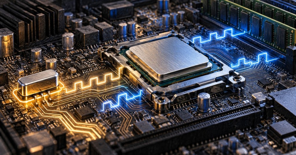
A modern computer can perform billions of operations per second, but the logic inside it cannot simply change whenever it wants. Most digital systems need a shared sense of when a value should be accepted, moved, or replaced. That timing reference is the clock signal: a repeating electrical signal that acts like a metronome for synchronous digital logic.
If you have ever seen a processor advertised at 4 GHz or 5 GHz, you have already encountered clock frequency. But GHz is only one part of the story. The clock does not directly tell you how many programs a computer can finish, how many instructions it executes per cycle, or how quickly data arrives from memory. To understand what the number really means, it helps to look at what the clock is physically doing inside a motherboard and processor.
The Clock Is an Electrical Rhythm
At its simplest, a clock signal repeatedly moves between a low electrical state and a high electrical state. On a diagram it often looks like a square wave: low, rising edge, high, falling edge, then low again. Digital circuits can use those transitions as precise moments when registers and other state-holding elements are allowed to capture new data.
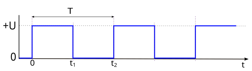
The key idea is not that every transistor flips on every clock cycle. Instead, the clock gives synchronous parts of the machine agreed-upon timing boundaries. Combinational logic has time to calculate an output between clock edges; then a register can capture that result on the next active edge. This repeated calculate-and-capture pattern is one of the foundations behind the way a CPU runs a program.
Frequency and Period Describe the Same Clock
Frequency tells us how many complete clock cycles occur each second. One hertz means one cycle per second. One megahertz means one million cycles per second. One gigahertz means one billion cycles per second.
The same clock can be described by its period, which is the amount of time required for one cycle. Frequency and period are reciprocals: f = 1/T. A 4 GHz clock therefore has a period of roughly 0.25 nanoseconds. That is an extraordinarily small timing window in which electrical signals must propagate through real transistors and wires.
Clock specifications also include concepts such as duty cycle, phase, rise time, and fall time. In actual digital design, clocks are constrained rather than treated as perfect theoretical square waves. Intel’s Timing Analyzer documentation, for example, defines clocks in terms of period and waveform edges so tools can determine whether data arrives within the required timing window.
Why the Edges Matter
Many synchronous circuits care more about an edge than about the clock remaining high or low. A flip-flop might capture its input on the rising edge, meaning the instant the signal transitions from low to high. Other designs use falling edges, and some high-speed interfaces transfer useful information on both edges.
This edge-based behavior makes timing measurable. Data generally must become stable shortly before a capturing edge and remain stable briefly afterward. Engineers call these requirements setup time and hold time. If a signal arrives too late, changes too early, or encounters too much noise, the receiving register may not capture the intended value reliably.
Where Does the Clock Come From?
A computer normally begins with a stable reference produced by an oscillator, often built around a quartz crystal or another precision timing source. That reference can feed clock-generation circuitry that creates the different frequencies needed throughout the system.
Modern processors commonly use a phase-locked loop, or PLL, to derive faster internal clocks from a lower-frequency reference. This is why a processor can receive a reference clock that is much slower than its advertised core frequency. Intel’s current processor reference-clock documentation describes base-clock inputs feeding internal PLLs that generate processor, interconnect, PCI Express, and memory-interface frequencies.
The resulting timing signal then has to be distributed across a chip. That sounds trivial until the chip contains billions of transistors spread across a physically large die. Clock networks are carefully designed so that one part of the chip does not see a supposedly simultaneous edge far earlier than another part.
One Computer Can Have Many Clock Domains
There is no single universal clock ticking identically through every component in a PC. CPU cores, memory controllers, graphics hardware, peripheral interfaces, and other subsystems can operate at different frequencies or derive timing from different sources. Engineers call regions that share a timing reference clock domains.
Moving information between domains needs care because the sender and receiver may not agree on exactly when a signal changes. Designers use synchronizers, buffers, handshakes, and asynchronous FIFOs to cross those boundaries safely. The same general timing problem appears in many forms of serial communication: useful data is only useful when the receiver knows when to sample it.
Why More GHz Does Not Automatically Mean a Faster Computer
A 5 GHz processor has a faster nominal core clock than a 4 GHz processor, but that alone does not prove it completes real work 25 percent faster. Performance also depends on how much useful work the architecture completes per cycle, how many cores are active, cache behavior, branch prediction, memory latency, instruction mix, power limits, software design, and many other factors.
That distinction is why benchmark results matter more than GHz alone when comparing unrelated processors. Clock frequency is a real engineering parameter, not a universal performance score.
Clock Speed Has Electrical and Thermal Costs
Raising clock frequency asks logic to complete its work in less time. Higher performance can also demand more voltage, which increases power consumption and heat. That is why overclocking a CPU is not simply a matter of choosing a larger number. The silicon, voltage regulation, cooling system, motherboard, firmware, and workload all determine whether the faster timing remains stable.
The reverse is also useful. Processors dynamically reduce frequency and voltage when full performance is unnecessary, then boost when workload and thermal conditions permit. If temperature becomes excessive, thermal throttling can lower frequency to protect the chip and keep operation inside safe limits.
Jitter, Skew, and Timing Closure
Real clock edges are not perfectly spaced. Small variations in when an edge arrives are called jitter. Differences in arrival time between destinations are called skew. At low speeds, tiny timing errors may leave plenty of margin. At multi-gigahertz speeds, however, fractions of a nanosecond become significant.
This is one reason advanced chip design is not just about making transistors smaller. Engineers must prove that signals can physically travel through logic and interconnects before the next required clock edge. Reaching that goal across manufacturing variation, voltage changes, and temperature is part of the broader problem known as timing closure.
The Practical Takeaway
Think of a computer clock as a distributed timing agreement. It creates recurring electrical moments that let digital logic move from one known state to the next. Frequency tells you how often those moments occur; the architecture determines how much useful work can happen between them.
So the next time you see a processor labeled 3.8 GHz, 5.2 GHz, or anything similar, read the number correctly: it is describing a clock rate for part of the machine, not the total speed of the computer. The remarkable engineering achievement is not merely making the clock fast. It is making billions of devices, wires, registers, and multiple clock domains behave reliably while those edges keep arriving billions of times every second.


Leave a Reply