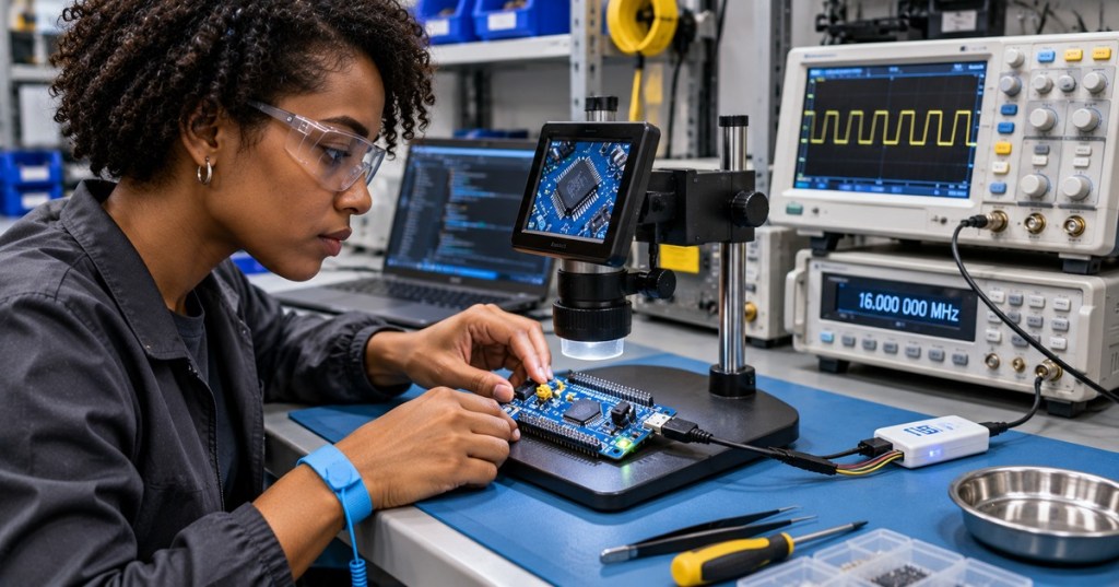
OSFTC.016 teaches the field diagnosis of microcontroller clock-source problems, including internal and external oscillators, phase-locked loops (PLLs), clock-ready flags, clock security and startup timing. A board can have a stable supply yet communicate at an unexpected serial baud rate, miss deadlines or fail to initialize a peripheral because its active clock differs from the firmware’s assumptions. An engineer or technician must establish which clock source was requested, which clock source became ready, and which clock actually drives the core and peripherals.
The lesson follows OSFTC.015, Brownout Reset Diagnostics, which distinguishes supply-voltage faults from software resets. Clock faults demand a different evidence trail. Earlier firmware crash-log training and hardware–firmware compatibility checks explain why a missing peripheral response or unexpected boot sequence should not automatically trigger reflashing.
Learning Objectives and Prerequisites
- Explain HSI, HSE, LSI, LSE, PLL, SYSCLK, HCLK and peripheral clock domains without assuming that all MCU families implement identical clocks.
- Identify clock startup, oscillator-ready flags, PLL lock, clock-switch confirmation, and clock security system (CSS) behavior.
- Use device documentation and read-only register inspection to differentiate a source that never stabilized from a source that was never selected.
- Calculate clock-divider outputs and compare expected timing with hypothetical observations.
- Understand why voltage scaling, Flash wait states, clock tolerances and board revision affect valid configurations.
- Document safe technician escalation when a missing clock, broken crystal, corrupt firmware setting or peripheral timing error is suspected.
Prerequisites: basic CPU architecture, timing units (hertz, microseconds, milliseconds), microcontroller reset causes, voltage measurement and UART diagnosis. No physical fault injection is necessary. The illustrated reference family is STM32L4, using STMicroelectronics reference manual RM0394, but all physical tests and register names must be checked for the exact part number and silicon revision.
Clock Sources and Their Different Jobs
A clock is a repeating timing signal used to sequence digital circuits. Some clocks run the CPU; others drive peripherals or low-power functions. An internal RC oscillator is built inside the MCU and often supports fast startup without a crystal. An external oscillator input may use a crystal resonator or a compatible external clock supplied by hardware. A PLL uses a reference clock to synthesize another frequency, subject to specific input, VCO and output limits.
- HSI: high-speed internal oscillator. The STM32L4 reference family provides an HSI16 oscillator nominally at 16 MHz. Accuracy and trimming must be evaluated for the actual device and environment.
- HSE: high-speed external clock path; may be a crystal circuit or bypassed external clock on a permitted board configuration.
- LSI and LSE: low-frequency sources typically relevant to functions such as the independent watchdog and RTC; a 32.768 kHz LSE crystal is common but not guaranteed to be populated on every design.
- SYSCLK: selected source for the system clock; after reset an STM32L4 device may initially use an internal MSI configuration before the application requests another source.
- HCLK and PCLK: downstream domain clocks determined by divider and bus configuration; individual peripheral kernel clocks may use additional independent selectors.
The ST RM0394 reset and clock control chapter specifies source selection, ready flags, PLL behavior and allowed operating frequencies for the L4 subfamilies it covers. The device family matters: a clock source or fallback used by one STM32 is not automatically available on another. A general BitcoinVersus.Tech introduction to clock signals provides broader background; the current chapter concentrates on hardware verification and technician diagnostics.
Startup Flags and the Crucial Distinction Between Ready and Selected
When firmware enables an oscillator, it should allow the source to settle and wait for a model-specific ready indication. A PLL likewise needs a valid input reference and a locked state before its output can be relied upon. A request to switch the system clock is not itself proof the switch occurred. The technician should compare the requested selection, the ready state, and the current source status documented for the chip.
For the STM32L4 device family in RM0394, the startup clock can be an internal MSI source. A target selection that is not yet ready may be held until the source becomes ready, and status bits identify the selected system clock. Avoid interpreting an incorrect baud rate or slow LED blink as proof the HSE crystal failed; peripheral prescalers, the firmware’s clock-variable calculation, timer configuration, serial framing and interrupt latency can produce similar symptoms.
STMicroelectronics, “STM32Cube tools in practice — STM32CubeMX, STM32CubeIDE — clock tree,” June 20, 2022. Official, freely available manufacturer training demonstrating clock configuration. The video uses teaching UI from its release period, which may differ from newer Cube tools.
Clock Security, PLL Fallback and Safe States
A clock security system monitors selected clock sources on supported devices. ST’s STM32 clock-system education describes HSE clock-failure detection and a possible automatic switch to an internal source. RM0394 documents a nonmaskable interrupt (NMI) linked to HSE CSS, along with MCU-specific flag-clearing requirements and restrictions. If HSE is the PLL’s input and fails, the PLL output may also be disabled. Recovery behavior, safe shutdown of motors and communications, and the fault record require application design, not a technician’s ad hoc configuration change.
Other vendors use different terminology. Microchip’s Fail-Safe Clock Monitor training documents clock-generator and PLL monitoring on its covered dsPIC family and the corresponding backup-clock and interrupt behavior. It should not be treated as a register guide for STM32 hardware. Neither clock security nor a watchdog guarantees that a safety-critical controller can continue safe control at the original timing performance after a fallback.
A clock problem may look like intermittent UART errors, inaccurate timestamping, missed watchdog servicing, a failed USB enumeration, or a peripheral that will not start. Some peripherals rely on clock domains independent of the CPU clock, and a fallback that saves code execution may still disrupt those peripherals. A correct incident report separates clock faults from voltage faults, software configuration defects, wiring faults and attached-device failures.
Calculate the Clock-Divider Effects
For a simplified bus divider, fAHB = fSYSCLK / D, where D is an allowed AHB divider. In an illustrative STM32L4 calculation, compare a 16 MHz internal HSI16 reference with an 80 MHz system-clock configuration that is within the specified maximum for an appropriate supported voltage-scaling range. At divider values 1, 2, 4 and 8, 16 MHz becomes 16, 8, 4 and 2 MHz, while 80 MHz becomes 80, 40, 20 and 10 MHz.
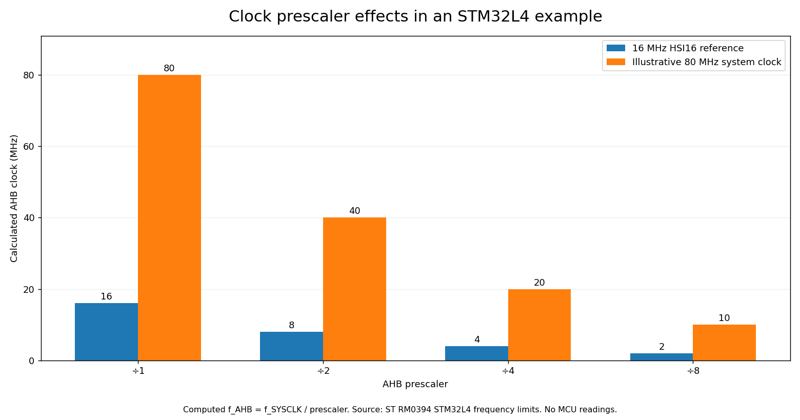
The chart illustrates a diagnostic trap: a correct 16 MHz oscillator may be followed by a divider of eight, producing a 2 MHz AHB clock. A sluggish application therefore cannot be assigned to a defective oscillator until the full clock-tree configuration is reviewed. An 80 MHz clock plan is not a license to run any device at 80 MHz; verify supply voltage, power mode, Flash latency and model-specific maxima before deployment.
A Repeatable Calculation Exercise
Technicians without hardware can reproduce the calculations using a standard Python 3 interpreter. The program accepts two hypothetical system-clock sources and computes divider outputs. The source below uses no hardware registers, test probes or board libraries; it is a documentation-only learning aid.
prescalers = (1, 2, 4, 8)
for source_mhz in (16, 80):
    print(f"{source_mhz} MHz SYSCLK:",
          [source_mhz / divide for divide in prescalers])
Expected output after running the program in Python 3:
16 MHz SYSCLK: [16.0, 8.0, 4.0, 2.0]
80 MHz SYSCLK: [80.0, 40.0, 20.0, 10.0]
The calculations were independently verified against the chart values. They do not prove which clock a live device is using. To verify actual hardware, a technician needs approved, board-specific readings from a debugger or a manufacturer-supported measurement point, and an instrument appropriate for the signal’s frequency and electrical level.
STMicroelectronics, “STM32CubeMX basics: 03.1 STM32CubeMX clock configuration tab — Basics,” March 27, 2019. An official educational walkthrough of STM32CubeMX clock configuration and its prerequisite toolchain. Settings and UI reflect the original training release.
Read-Only Field Diagnosis Workflow
- Record identity before testing: obtain the full MCU order code, board revision, current firmware/build identifier, supply design and clock design documents. Note whether HSE comes from a crystal or an external clock output.
- Verify the symptom and state: record power-up pattern, reset causes, UART/USB/network behavior, error timestamps, environmental conditions and any peripherals failing to initialize.
- Review the firmware’s intended clocks: identify oscillator choices, PLL settings, multipliers, dividers, voltage scaling, flash wait states and peripheral clock selectors in its configuration or generated initialization code.
- Read clock status without modifying it: if supported and permitted, record the relevant RCC source-selection, ready, PLL lock and CSS diagnostic flags. A debug connection may itself affect timing or low-power behavior.
- Compare expected and observed timebases: measure a manufacturer-approved MCO or other permitted frequency output only if qualified, using suitable high-impedance equipment. Avoid probing crystal terminals merely because they look accessible.
- Separate failure classes: distinguish never-ready external source, PLL lock failure, wrong system-clock selector, bus-divider mismatch, peripheral kernel-clock selection or supply-related reset.
- Preserve the evidence: attach device ID, register snapshot, log excerpt, voltage state, toolchain version, clock configuration, instrument settings and change-control number to the fault report.
- Escalate safely: recommend manufacturer-guided analysis and firmware/hardware review rather than bypassing the clock security system or substituting an unapproved external clock.
Common Failure Patterns and Diagnostic Limits
- HSERDY never asserts: possible disabled HSE, absent oscillator hardware, incorrect crystal/load network, unsuitable external-clock mode or faulty hardware; the symptom is not proof of a cracked crystal.
- PLLRDY does not assert: check the reference source, divider/multiplier plan, permitted frequency ranges and firmware initialization sequence.
- HSERDY ready but SYSCLK unexpected: the source may be stable but not selected; inspect the confirmed clock switch status rather than the enable bit alone.
- UART is unreliable: compare actual peripheral clock, baud generator, terminal settings and frequency tolerance before replacing a crystal.
- CPU seems slow: verify AHB and APB prescalers, active clock source and low-power mode; not every apparent speed loss is a reset or oscillator problem.
- RTC drifts or stops: distinguish LSE/LSI selection and calibration from the main HSE/PLL clock path; low-speed clocks may continue independently.
- CSS fault occurred: document the triggering source, current fallback, clock-dependent peripherals, and safe-state behavior before any recovery intervention.
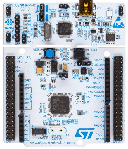
An inactive CPU clock is not a reason to attach a scope probe to a crystal pin: added probe capacitance may disturb or stop oscillation. Work only on isolated training hardware under approved engineering procedures; any contact with energized systems, industrial control equipment, or oscillator networks needs suitable supervision and tools. ST’s NUCLEO-L476RG product page and board manual UM1724 supply real board identification resources.
Practical Lab and Knowledge Check
Documentation-only lab: examine the hypothetical chart and identify the resulting AHB clock when a nominal 80 MHz system clock is divided by four. Answer: 20 MHz. Calculate a nominal 16 MHz clock’s period: 1/16,000,000 seconds = 62.5 nanoseconds. Then write a mock technician ticket for a board that announces an HSE timeout but continues on HSI. List at least three possible causes and the evidence necessary to distinguish them without making a register write.
- Does HSERDY prove that HSE drives SYSCLK? No. Ready status and active-source status are distinct.
- Does a working 16 MHz HSI prove an external crystal works? No. These are separate sources.
- What does PLL lock indicate? The synthesizer is ready under the device’s documented lock definition; it does not establish that every peripheral is timed correctly.
- Can CSS fallback preserve every timing function? No. Some peripherals and real-time constraints may no longer be satisfied.
- What is 80 MHz ÷ 8? 10 MHz; confirm the AHB divider actually equals eight before using that value.
- Why must exact device documentation be used? Clock options, register flags, startup clocks, limitations and failover behavior vary among MCU families and revisions.
- Is reflashing a firmware image the correct first diagnostic step for a suspected bad crystal? Not automatically. Preserve evidence and examine actual clock selection, board population, voltage and logs.
Official and Open Educational References
STMicroelectronics, STM32L4 reference manual RM0394; ST educational clock-security article; ST NUCLEO-L476RG product page; Microchip Developer Help, Fail-Safe Clock Monitor; and Open-CMSIS-Pack board-support repository. The embedded STM32Cube training videos are official public instruction, not recordings of the present laboratory example.
Conclusion
Reliable clock diagnostics begin with an exact hardware identity and end with a verified distinction among oscillator startup, PLL lock, active selection, divider configuration and peripheral timing. Clock failures and power resets can have overlapping symptoms; the evidence should be recorded separately. Correct diagnosis protects functioning hardware from unnecessary reflash, replacement and unapproved modification.
Editor’s Note: OSFTC.016 follows the published brownout diagnostics lesson OSFTC.015. The 1200 × 630 featured image is original conceptual AI editorial art featuring a younger technician to rotate the cover roster; its waveforms and instrument readings are fictional, not measured board values. The genuine NUCLEO-L476RG equipment photograph is sourced to the Open-CMSIS-Pack board repository. The engineering bar chart uses calculated frequencies derived from stated ST RM0394 assumptions, not a live device. The Python calculation was checked, while no microcontroller registers were read or altered and no oscilloscope measurement or clock failure was conducted. The two videos are historical official STMicroelectronics educational material; rendered player presence and live playback are audited separately.

On a phone, display the QR on a second screen or use a compatible wallet’s saved-image scanner where supported. Verify the recipient and 5,000-satoshi amount before authorizing the optional donation.
We volunteer daily to ensure the information on this platform is Verifiably True. If you would like to support the research, please scan the QR code.
BitcoinVersus.Tech offers educational information, not individualized electrical or safety certification. Live testing must follow site procedures and qualified supervision.


Leave a Reply