Elementary Overview
OSFTC.017 explains how a microcontroller creates carefully timed electrical pulses and how a firmware technician can verify the pulses without guessing. A timer inside the chip counts regular clock ticks. It can turn a digital output on for part of each cycle and off for the remaining part, producing a pulse-width-modulated signal, commonly called PWM. PWM can control an LED’s apparent brightness, regulate a suitable fan-controller input or provide a command to a motor driver. The waveform is a timed digital signal, not an adjustable analog voltage.
A signal that looks steady to the eye can still have the wrong frequency, duty cycle, voltage level or output route. A technician checks the approved expected values, reads the timer configuration and confirms the result with a properly connected oscilloscope or logic analyzer. The preceding OSFTC.016 clock-source diagnostics covered oscillator and phase-locked-loop problems; a timer’s behavior depends on the clock path examined there.
Learning goals: distinguish PWM period, frequency and duty cycle; explain prescaler (PSC), auto-reload (ARR) and capture/compare (CCR) settings; calculate expected waveforms; identify clock-tree and pin-routing mistakes; perform a low-voltage instrument check; and document evidence before changing firmware or hardware.
Official STMicroelectronics training: Hands-On with STM32 Timers: Custom Signal Generation using PWM and DMA, Part 1. Demonstrates a real STM32 Nucleo board, STM32CubeIDE and timer PWM output on a selected channel. Watch the original manufacturer video.
What timer hardware measures
Many STM32 microcontrollers provide timers with a clock input, counting register, prescaler, period register, channel comparison registers and output-control logic. The prescaler reduces the counter tick rate. An auto-reload value defines the counter rollover in ordinary edge-aligned up-counting. A compare value determines when the channel changes its logical output state. The official STMicroelectronics Getting started with TIM reference introduces these settings and STM32CubeMX configuration.
For common edge-aligned up-counting PWM mode 1, with active-high output and a timer clock called fTIM, the counter clock is approximately fcounter = fTIM / (PSC + 1). If the counter runs from zero through ARR, the ordinary PWM repetition frequency is fPWM = fcounter / (ARR + 1). For a compare value between zero and one complete period, the ideal active-high duty fraction is D ≈ CCR / (ARR + 1). These relationships describe one specific counting and output mode, not every timer family.
A timer input clock is not always identical to the CPU frequency or the peripheral bus frequency. Some STM32 clock trees multiply a timer clock relative to a divided APB bus clock, while other families use different rules or selected kernel clocks. A technician must consult the particular chip’s clock-tree documentation, peripheral registers and debug readback. Treating SystemCoreClock as every timer clock can yield a factor-of-two error.
Worked timer calculation
Teaching example: suppose a general-purpose timer receives an 80 MHz clock. The configured prescaler register is PSC = 79, giving 80,000,000 / 80 = 1,000,000 counter ticks/s. The auto-reload register is ARR = 999, so the counter completes 1,000 ticks per PWM period. Frequency becomes 1,000,000 / 1,000 = 1,000 Hz, or 1 kHz.
For active-high, edge-aligned PWM mode 1, choose CCR = 250. The ideal duty fraction is 250 / 1,000 = 25%. Period is 1 / 1,000 Hz = 1.00 ms; an oscilloscope should therefore show approximately 0.25 ms high and 0.75 ms low, assuming the output is enabled and no load distorts the waveform. These are calculations for a hypothetical timer, not measurements from physical hardware.
Do not interchange the software’s desired pulse width, a driver API argument called pulse, and the raw register value without reviewing its documentation. Likewise, center-aligned counting traverses the count range in both directions and changes the relation between counter clock and waveform frequency. Output inversion, PWM mode 2, dead-time, complementary channels and special 0% or 100% behavior may alter observed pins. Advanced timers can also require a main-output-enable setting and a nonasserted break input.
Inspecting the signal safely
Use an authorized, isolated low-voltage development setup and the instrument manufacturer’s lead and grounding instructions. Many bench oscilloscopes have protective-earth-referenced probe grounds. Connecting that ground clip to a live or floating high-voltage node can create a short and an electric-shock hazard. Never use a standard grounded oscilloscope clip to investigate mains, inverter phases, power stages or other unknown-voltage nodes. A qualified technician must select an appropriately rated differential or isolated measurement arrangement when required.
- Establish the safe baseline: identify board model, power source, expected logic level, signal frequency, duty cycle, output pin and connector reference ground.
- Review firmware settings: record timer clock source, PSC, ARR, CCR, PWM mode, edge/center alignment, output polarity, preload, timer enable and peripheral ownership.
- Trace pin routing: check the MCU alternate-function selection, board schematic, pin mapping, pull configuration and any external transistor, buffer or isolator between the timer and the accessible test point.
- Measure carefully: connect a suitably rated probe to an authorized low-voltage test point, choose an appropriate voltage range and time base, then record period, positive pulse width, duty percentage and logic levels.
- Compare evidence: distinguish absent switching, incorrect frequency, incorrect duty cycle, inverted polarity, jitter and load-induced distortion. Capture settings, screenshots and firmware version.
- Recover deliberately: change only approved parameters, rerun the same measurement, and retain previous configuration and results for rollback.
For an unrelated microcontroller reset during testing, check supply integrity and the diagnostic context before blaming PWM. The existing brownout reset diagnosis and watchdog timer lesson cover two distinct causes of unexpectedly interrupted output.
Official STMicroelectronics training: Hands-On with STM32 Timers: Complementary Variable Frequency PWM. Shows a manufacturer demonstration of center-aligned operation and complementary outputs; those advanced cases require their own timing and safety analysis. Watch the original manufacturer video.
Troubleshooting common mismatches
No waveform: the timer may be stopped, a channel disabled, a GPIO set to ordinary output rather than the correct alternate function, the wrong physical test point selected, or an advanced timer’s output gate disabled. A PWM configuration inside software does not guarantee an active pin. Begin with pin routing and the read-only state of output-enable settings, not arbitrary register writes.
Frequency differs by a factor of two: first compare timer clock and bus clock, then verify counting alignment. Frequency off by a smaller fixed ratio: examine prescaler and ARR off-by-one assumptions. Duty wrong but frequency right: inspect CCR, output polarity, preload behavior, PWM1/PWM2 selection and whether the measurement refers to positive pulse width or active time.
Jitter or unstable pulse width: distinguish a hardware-timer output from software bit-banging under interrupt load. Real hardware PWM can run without toggling its pin on every CPU interrupt. CPU scheduling may still affect when firmware updates CCR or ARR; DMA transfers, preload settings, bus contention and clock behavior may matter. The firmware crash-log lesson provides broader diagnostic evidence collection practices.
A logic analyzer may show edges and duty cycle, but it generally does not reveal analog rise time, overshoot, ringing or insufficient logic-high amplitude. An oscilloscope can show those voltage-domain defects if its bandwidth, sampling, probes and grounding arrangement are suitable. The instrument’s displayed measurement remains subject to calibration and uncertainty.
Input capture is a different test
Some timers can also measure an incoming waveform using input-capture channels. Captured counter values at successive edges reveal period or pulse width when interpreted with the timer’s actual clock and rollover handling. That mode is different from output-compare PWM generation. The Microchip PWM technical brief offers a separate implementation of capture/compare/PWM principles; register names and timer structures vary across MCU vendors.
For a test in which an expected 1 kHz PWM is measured as 1.02 kHz, the absolute deviation is 20 Hz and relative deviation is (1,020 − 1,000) / 1,000 × 100 = +2%. Before calling the result a timer fault, establish instrument accuracy, clock tolerance, actual configuration, measurement gate duration and acceptable system requirements. No universal ±2% pass/fail rule is implied.
Official STMicroelectronics training: Hands-On with STM32 Timers: Internal Triggering System. Demonstrates linked hardware timers and phase-shifted PWM, illustrating why timer synchronization must be identified before comparing channels. Watch the original manufacturer video.
Practical documentation exercise
Using only the hypothetical 80 MHz example, write an acceptance record containing source clock 80 MHz, PSC 79, ARR 999, CCR 250, edge-aligned PWM1, active-high output, target 1 kHz and 25% duty, calculated period 1.00 ms, and expected high interval 0.25 ms. A blank observation field must remain blank until a qualified operator performs an actual measurement. Record measured and expected quantities separately.
A valid engineering record also includes the exact MCU and board revisions, firmware build, pin location, instrument calibration identifier, probe configuration, screenshot filename, ambient conditions if relevant, technician, timestamp and test authorization. When updating firmware, preserve the backup and recovery workflow before changing timer initialization.
Knowledge check
Question: With an 80 MHz timer clock and PSC of 79, what is the counter tick rate? Answer: 1 MHz, because the divider is PSC + 1 = 80.
Question: For ARR of 999 and CCR of 500 in the stated PWM mode, what ideal active-high duty fraction is expected? Answer: 50%, because 500 / 1,000 = 0.5.
Question: Does seeing 1 kHz on a logic analyzer prove electrical amplitude and edge quality? Answer: No. Those properties require suitable analog measurement.
Primary technical references
- STMicroelectronics, Getting started with TIM, official guidance for STM32 timer configuration, prescalers and PWM.
- STMicroelectronics STM32Cube software documentation, device-specific example packages; consult the matching family reference manual.
- Microchip Technology, Getting Started with PWM, official CCP/PWM principles and example configurations.
- Microchip Technology, How to Select a Timer on PIC MCUs, timer mode comparison and application context.
Elementary Conclusion
A timer is a small clock-based counter built into the microcontroller. PWM uses the counter to repeat an on/off signal at a chosen rate and with a chosen share of time on. By checking the timer clock, prescaler, period, compare setting and actual output pin, a technician can find out why the real signal differs from the intended one. The safest diagnosis combines exact calculations with carefully authorized low-voltage measurements.
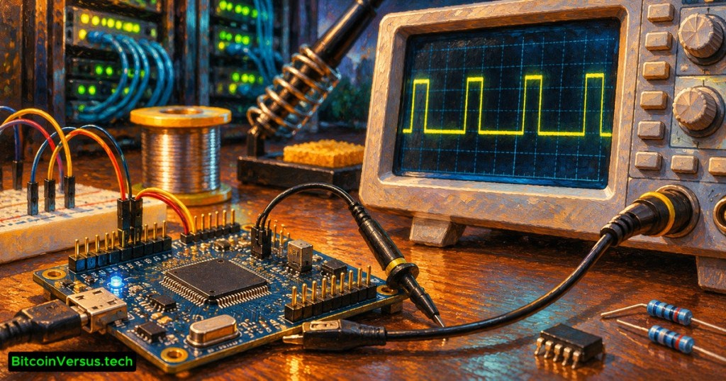
Editor’s Note: The examples are instructional calculations checked against official STMicroelectronics and Microchip materials. The featured oil painting is original AI-generated editorial art, not a photograph of an operational lab. All three in-body videos are genuine STMicroelectronics training entries. WordPress may render YouTube iframes without independent confirmation that a particular device can play them. No electrical bench testing, firmware upload, oscilloscope hookup or live-hardware verification was performed. Safety limitations, model-specific differences and measurement uncertainty remain essential.

BitcoinVersus.Tech is volunteer-run and publishes independent technical education. An optional 5,000-satoshi contribution supports research. Scan the QR using a second screen or import a saved QR image into a compatible wallet. Independently confirm the destination 3C9o19EH5HSiwEPyCTmEKzxhNCbo2X6TTb and amount; Bitcoin payments are generally irreversible.
We volunteer daily to ensure the information on BitcoinVersus.Tech is Verifiably True. Educational content is not permission to perform hazardous electrical testing, and does not replace equipment-specific service manuals or qualified supervision.


Leave a Reply