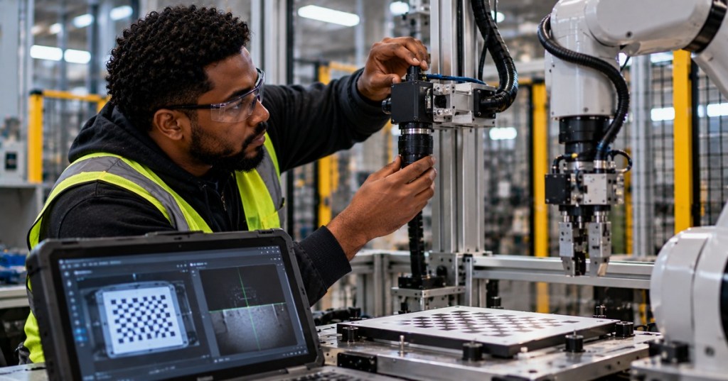
Robot vision calibration creates a reliable geometric relationship between what a camera sees and where a robot can move. A camera may detect a part perfectly in pixel coordinates and still send the robot to the wrong physical location if the camera model, work plane, tool center point, robot frame, or hand-eye transform is wrong.
This lesson follows OSRTC.007: Robot Preventive Maintenance. Preventive maintenance establishes the mechanical and electrical baseline. Vision calibration adds another baseline: camera position, lens settings, lighting, calibration target, robot TCP, frames, and coordinate transforms must remain consistent enough for the vision-guided process to be repeatable.
FANUC America — official iRVision overview covering machine-vision camera and robot calibration methods.
Learning Objectives
- Distinguish camera calibration from robot-to-camera hand-eye calibration.
- Explain intrinsic and extrinsic camera parameters in technician terms.
- Identify eye-in-hand and eye-to-hand vision arrangements.
- Understand why TCP, user frames, calibration targets, focus, exposure, and lighting affect accuracy.
- Use reprojection error and physical verification points to judge calibration quality.
- Troubleshoot offset, rotation, scale, drift, and intermittent vision-guidance errors systematically.
Start With Safety and a Stable Workcell
Vision calibration often requires deliberate robot motion while a target or camera is inside the work envelope. Follow the workcell risk assessment, manufacturer instructions, reduced-speed/manual-mode requirements, safeguarding rules, and facility procedures established in OSRTC.001. Do not bypass a safety device just to obtain a calibration pose.
Before collecting calibration data, mechanically stabilize the cell. Confirm the robot base, camera bracket, lens, calibration plate, fixture, and tool are secure. If the camera or target can move during data collection, the computed transform may fit inconsistent measurements and produce misleading results.
What Camera Calibration Actually Solves
A camera converts points in the physical world into image coordinates. Camera calibration estimates the parameters needed to model that conversion. OpenCV separates these into intrinsic parameters, which describe the camera itself, and extrinsic parameters, which describe camera pose relative to another coordinate system.
- Focal length: represented by focal scaling terms such as fx and fy.
- Principal point: the optical center location cx, cy in the image model.
- Lens distortion: coefficients that account for radial and tangential distortion.
- Rotation and translation: parameters that describe the camera pose relative to a known target or world frame.
OpenCV’s calibration documentation explains that known 3D target points and their observed 2D image positions are used to estimate these parameters by minimizing reprojection error. Industrial systems often hide the mathematics behind guided calibration screens, but the geometry is the same.
Intrinsic Calibration Is Not Hand-Eye Calibration
Intrinsic calibration answers: “How does this camera and lens map the scene onto pixels?” Hand-eye calibration answers: “Where is this camera coordinate system relative to the robot?” A vision system can have excellent lens calibration and still guide the robot incorrectly if the hand-eye relationship is wrong.
Cognex describes hand-eye calibration as establishing a transform between robot space and camera space. In practice, the robot and vision system observe corresponding reference points or poses, then compute the coordinate transformation that lets a detected object position become a robot-reachable position.
A 2026 robotics discussion compares practical camera-calibration workflows and highlights how calibration remains a real integration task across USB, GigE/GenICam, CSI, ROS, and OpenCV-based systems.
Eye-in-Hand Versus Eye-to-Hand
Two common layouts appear in industrial cells. In an eye-in-hand system, the camera is mounted on the robot or end effector and moves with it. In an eye-to-hand system, the camera is fixed in the cell and observes the robot workspace from a stationary location.
- Eye-in-hand: camera motion must be related accurately to robot motion; cable routing and camera bracket rigidity matter.
- Eye-to-hand: camera-to-cell geometry must remain fixed; fixture or camera movement can shift every guided pick.
The calibration procedure depends on the vendor and application, but both layouts ultimately need reliable transforms between the camera, robot, tool, and workpiece coordinate systems.
TCP Accuracy Matters Before Vision Accuracy
If the robot uses a tool point to touch a calibration grid or reference feature, the TCP must already be accurate. A TCP error becomes input error in the vision calibration. Review OSRTC.004: End Effectors and Tool Center Point Setup before blaming a camera for an offset caused by the tool definition.
Likewise, incorrect robot mastering can shift the physical relationship between commanded joint positions and actual arm geometry. If a robot has recently lost mastering or suffered a mechanical event, verify the robot reference condition using OSRTC.003 before recalibrating the vision system.
Calibration Targets Need Known Geometry
Chessboards, dot grids, ChArUco boards, coded targets, and vendor-specific plates provide features whose spacing and geometry are known. OpenCV supports planar chessboard-style targets; industrial systems may use proprietary grids or precision plates.
Use the target exactly as required by the procedure. Wrong square size, wrong dot spacing, a damaged plate, poor print scale, warped mounting, contamination, or entering rows and columns in the wrong order can create a mathematically valid-looking calibration with incorrect physical scale.
Use Many Useful Views, Not Many Identical Views
Calibration quality improves when the target is observed across meaningful positions and orientations. OpenCV recommends multiple board poses with significant tilt and coverage across the expected working-distance range because nearly identical views provide nearly identical geometric information.
For a technician, this means avoiding a calibration set made of ten images that all look the same. Cover the useful field of view, include different orientations when the procedure allows, avoid clipping the target, and maintain good feature contrast.
FANUC America — official 3DL calibration demonstration showing the relationship among the calibration grid, robot frame, camera location, and multiple acquisition poses.
Focus, Exposure, Lighting, and Resolution Are Part of Calibration
Geometry cannot rescue a poor image. Before calibration, set focus, aperture if adjustable, exposure, gain, lighting, polarization, working distance, and acquisition resolution for the real production condition. Feature edges must be stable enough for the vision tool to locate the same geometry repeatedly.
Cognex calibration guidance warns that changing the physical relationship among the vision sensor, lens, and scene can invalidate calibration. Changing image resolution or moving the sensor can also invalidate the computed mapping. Treat camera mounting and acquisition settings as controlled configuration, not casual operator preferences.
Reprojection Error Is Useful but Not the Final Proof
Calibration software often reports an RMS or average reprojection error. This measures how closely the estimated model projects known target points back onto their observed image positions. A lower error generally indicates a better mathematical fit, but it does not prove the entire robot application is correct.
A low reprojection error can coexist with a wrong target scale, wrong robot frame, bad TCP, moved fixture, or incorrect hand-eye transform. The pass condition is physical verification: command or guide the robot to independent known points across the working area and confirm the error is acceptable for the process.
Verify More Than the Center of the Image
A weak calibration can appear accurate near the center and degrade near the edges. Verify multiple points across the actual working envelope. Check near corners, different heights if the process is three-dimensional, and representative part orientations.
Record measured error by location. If the error grows systematically across the field, that pattern is evidence. It may point toward incorrect scale, lens distortion, an invalid work plane, poor target coverage, camera tilt, or transform error.
Common Error Patterns
- Constant X/Y offset everywhere: inspect TCP, user frame, camera-to-robot translation, fixture reference, and target origin.
- Error changes with rotation: inspect tool orientation, rotational transform, TCP, part-angle convention, and Euler-angle convention.
- Scale error that grows with distance: inspect calibration target dimensions, working plane, camera model, resolution, and lens calibration.
- Good center / bad edges: inspect lens distortion, target coverage, focus, field of view, and calibration-image diversity.
- Drift over time: inspect camera bracket movement, lens movement, thermal change, robot mastering, fixture shift, loose fasteners, and cable strain.
- Intermittent missed features: inspect lighting, reflections, exposure, motion blur, trigger timing, contamination, focus, and part presentation.
- Correct image result / wrong robot move: separate the vision result from the robot transform and I/O path; verify each layer independently.
A 2026 robotics discussion about a calibration target illustrates how coded and checkerboard-style reference patterns are used to provide known visual geometry for robot and camera calibration.
Trigger Timing Can Look Like Geometry Error
In moving-camera or moving-part applications, the exact instant of image acquisition matters. Cognex notes that hand-eye applications can show directional drift if the trigger point changes relative to motion. Encoder timing, network delay, exposure time, robot motion, conveyor tracking, and camera trigger configuration can therefore create apparent spatial error.
If static verification is accurate but moving production is wrong, do not immediately recalibrate. Compare static and dynamic behavior. A timing problem can survive repeated geometric recalibration because the geometry was never the root cause.
Network and I/O Problems Can Masquerade as Vision Problems
A vision-guided pick often depends on a chain: trigger request → image acquisition → vision result → coordinate conversion → robot/PLC handshake → motion command. Use the signal-path reasoning from OSRTC.005. Confirm that the correct result belongs to the correct part and cycle before changing calibration.
Watch for stale results, duplicated triggers, dropped handshakes, wrong job files, wrong camera IP addresses, mismatched recipe selection, and coordinate data arriving in the wrong units or order.
A Technician Troubleshooting Sequence
- Capture the exact failure before changing anything: offset direction, magnitude, part orientation, camera job, robot program, frame, and cycle conditions.
- Verify robot mastering, TCP, payload, user frame, and fixture condition.
- Inspect the camera, lens, bracket, lighting, target, cables, connectors, and protective window for physical change.
- Confirm the correct camera job, resolution, exposure, focus, trigger mode, and calibration file are loaded.
- Test the vision result in camera coordinates without robot motion.
- Test the camera-to-robot coordinate transform with known reference points.
- Compare center and edge accuracy across the field of view.
- Review calibration residual or reprojection error, but do not accept it as the only proof.
- Test static accuracy before dynamic accuracy.
- If the failure occurs only during motion, investigate trigger timing, conveyor tracking, robot velocity, communication delay, and exposure.
- Recalibrate only after confirming that calibration is actually invalid.
- After recalibration, verify independent physical points that were not used to compute the calibration.
Hands-On Exercise
Using a training cell, simulator, or vision development environment, collect calibration images of a known checkerboard or grid at several positions and angles. Record the resulting calibration error. Then intentionally create one controlled fault at a time: move the camera slightly, change image resolution, enter the wrong grid spacing, or shift the robot TCP in simulation.
For each fault, predict the error pattern before testing. Classify what you observe as mostly offset, rotation, scale, edge distortion, or intermittent detection. Restore the correct configuration and verify that the original accuracy returns.
Knowledge Check
- What is the difference between intrinsic camera calibration and hand-eye calibration?
- Why can a bad TCP corrupt robot vision calibration?
- What is the difference between eye-in-hand and eye-to-hand vision?
- Why should calibration images include varied positions and orientations?
- What does reprojection error measure?
- Why is low reprojection error not sufficient proof of robot accuracy?
- What type of fault can cause good static accuracy but poor accuracy during motion?
- What should a technician check when error grows toward the edges of the image?
Answers
- Intrinsic calibration models the camera/lens and image formation; hand-eye calibration establishes the camera-to-robot coordinate relationship.
- If the TCP is used as a physical reference, its position error becomes calibration input error.
- Eye-in-hand places the camera on the moving robot; eye-to-hand keeps the camera fixed in the cell.
- Different views provide stronger geometric information and help constrain the camera model across the useful field and distance range.
- The pixel-space difference between observed calibration features and where the estimated model projects those features.
- The robot can still have the wrong TCP, frame, scale, transform, or fixture relationship even if the camera model fits its calibration images well.
- Trigger timing, motion blur, conveyor tracking, latency, or other dynamic synchronization problems.
- Lens distortion, calibration-target coverage, focus, working plane, camera model, and calibration-view diversity.
Previous Related Lessons
- OSRTC.007: Robot Preventive Maintenance
- OSRTC.006: Robot Alarm and Fault Recovery
- OSRTC.005: Robot I/O and PLC Handshakes
- OSRTC.004: End Effectors and Tool Center Point Setup
- OSRTC.003: Robot Mastering and Calibration
Primary references: Cognex — In-Sight Calibration Guidelines, Cognex — In-Sight 3D-L4000 Hand-Eye Calibration, OpenCV — Camera Calibration, and FANUC — iRVision 2D training.
BitcoinVersus.Tech Editor’s Note:
We volunteer daily to ensure the credibility of the information on this platform is Verifiably True. If you would like to support to help further secure the integrity of our research initiatives, please donate using the QR code provided
BitcoinVersus.Tech provides technical education and analysis for informational purposes only.


Leave a Reply