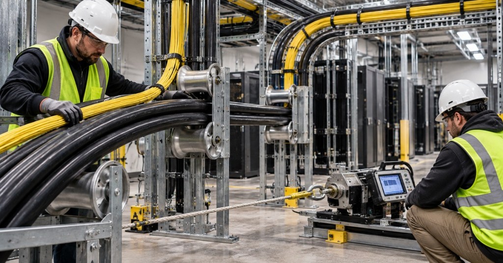
A cable can leave the reel looking perfect, arrive at the rack looking perfect, and still have been damaged somewhere in between.
That is the problem pulling tension creates. When technicians install fiber optic cable, Ethernet cable, control cable, or heavy power cable through conduit and trays, the cable is not only bending. It is also being stretched, pressed against bends, dragged across surfaces, twisted, squeezed by grips, and forced through changes in direction.
Our previous story explained why fiber, Ethernet, and power cable use different bend-radius rules. Pulling tension is the next part of the same physical-layer problem: a legal bend radius does not automatically make a cable pull safe.
Pulling Tension Is the Force Along the Cable
Pulling tension is the longitudinal force used to move a cable through its pathway. If the pull becomes harder because of distance, friction, bends, crowded conduit, poor roller placement, or an obstruction, the installer naturally wants to pull harder. Every cable has a point where “pull harder” becomes “damage the cable.”
For fiber, the Fiber Optic Association says the cable manufacturer’s maximum pulling-tension rating must not be exceeded and that pulling force should normally be transferred through the cable’s strength members rather than directly into the fibers. FOA also recommends approved pulling grips, swivel pulling eyes, tension control on longer pulls, compatible lubricant where appropriate, and figure-eight handling for intermediate fiber pulls.
That distinction is important. The glass fibers carry the data. Aramid yarn, fiberglass rods, messenger wire, or other strength members are there to carry mechanical load. Pulling the wrong part of the cable can send force into components that were never designed to take it.
Ethernet Has a Surprisingly Low Pulling Limit
For standard four-pair balanced twisted-pair cabling, ANSI/TIA-568 guidance limits installation pulling tension to 110 newtons, or 25 pounds-force. That is not much force. A technician can exceed it quickly by yanking on a snagged cable bundle.
The reason is geometry. Cat5e and Cat6 depend on tightly controlled conductor twists and spacing. Excessive tension can stretch conductors, deform the jacket, disturb pair geometry, or reduce the electrical margin that protects the link from insertion loss and crosstalk problems. The cable may still negotiate a link and still no longer be a healthy certified channel.
This is why proper structured cabling treats the pull as part of link performance, not merely the transportation step before RJ45 termination.
Sidewall Pressure Is What Happens at the Bend
Heavy power cable introduces another term technicians should know: sidewall pressure, sometimes called sidewall bearing pressure. Pulling tension acts along the cable. When that tensioned cable rounds a bend, the cable presses sideways against the conduit, roller, or sheave.
For a single cable or a multiconductor cable under one common jacket, the basic relationship is:
Sidewall pressure = pulling tension ÷ bend radius
So if the tension coming out of a bend is 900 pounds and the bend radius is 3 feet, the sidewall pressure is 300 pounds per foot. Increase the radius to 6 feet and the same 900-pound pull produces only 150 pounds per foot. This is why a larger sheave can make a difficult pull mechanically safer even if both sheaves satisfy the cable’s static minimum bend radius.
Southwire’s power-cable installation guide describes excessive sidewall pressure as one of the most restrictive factors in many cable pulls. Its examples also show why the final bend can be especially demanding: pulling tension accumulates through the route, so a later bend can see more tension than the earlier ones.
Friction Turns Length Into Force
A straight 30-foot pull and a 1,000-foot pull through multiple bends are completely different mechanical jobs. Every foot of contact adds friction. Every bend changes direction and can multiply tension. A crowded pathway can make neighboring cables another friction surface. Dirt, water, conduit condition, and the jacket material can all change the coefficient of friction.
This is why cable lubricant is not just about making the installer’s life easier. On approved cable and conduit combinations, compatible lubricant can reduce the force needed to move the cable and therefore reduce both pulling tension and sidewall pressure. The lubricant still has to be compatible with the jacket material and the project specification.
Pull Direction Can Change the Entire Calculation
The same pathway can be an easy pull in one direction and a bad pull in the other. If the most severe bend is near the beginning of the route, the cable reaches that bend before much tension has accumulated. Reverse the pull and that same bend may now be near the end, where it sees nearly the full accumulated pulling force.
That is why large industrial cable pulls are planned rather than improvised. Reel location, pull direction, conduit fill, bend sequence, elevation change, roller spacing, sheave size, lubrication, pulling-eye method, and winch location can all affect the final stress on the cable.
Fiber Needs the Right Grip, Not Just More Muscle
Fiber cable can contain aramid yarn, central strength members, fiberglass rods, armor, or messenger elements depending on the design. The correct pulling attachment depends on that construction. A pulling grip that works well on one cable can crush or slip on another.
FOA guidance emphasizes using the cable’s intended strength members and a swivel pulling eye where appropriate. The swivel matters because a pull rope can twist under load. Without a swivel, that torsion can be transferred into the cable and stress the fibers.
Preterminated fiber adds another layer because the LC, SC, MPO, or MTP connectors themselves must be protected inside a pulling assembly while the mechanical load is transferred into the cable’s strength system rather than the connector bodies.
A Dynamometer Is Better Than “Feels About Right”
On larger pulls, human judgment is a poor tension meter. Powered capstans and winches can generate far more force than a person realizes, especially when the cable starts to bind. A dynamometer, calibrated tension monitor, controlled puller, or engineered breakaway device gives the crew an actual limit instead of a guess.
FOA specifically recommends monitoring tension on longer outside-plant pulls and treating a breakaway swivel as a fail-safe rather than the primary measurement tool. If a cable is valuable enough to require OTDR testing and careful splicing afterward, it is valuable enough to protect while it is being installed.
Seven Signs the Pull Should Stop
- The required force suddenly rises. A hard stop often means a snag, jam, bad roller, conduit obstruction, or cable crossing.
- The cable starts flattening or changing shape. Visible deformation is not normal workmanship.
- The reel is feeding poorly. Cable should come off the reel in the intended direction without adding uncontrolled twist.
- A roller stops turning. The cable is now sliding across a surface instead of rolling over it.
- The pulling grip slips or walks. Stop before concentrated pressure damages the jacket or strength members.
- The monitored tension approaches the manufacturer limit. The limit is a ceiling, not a production target.
- The crew has to start yanking. Repeated shock loading is a sign to diagnose the route instead of adding more force.
The Cable Still Needs Protection After the Pull
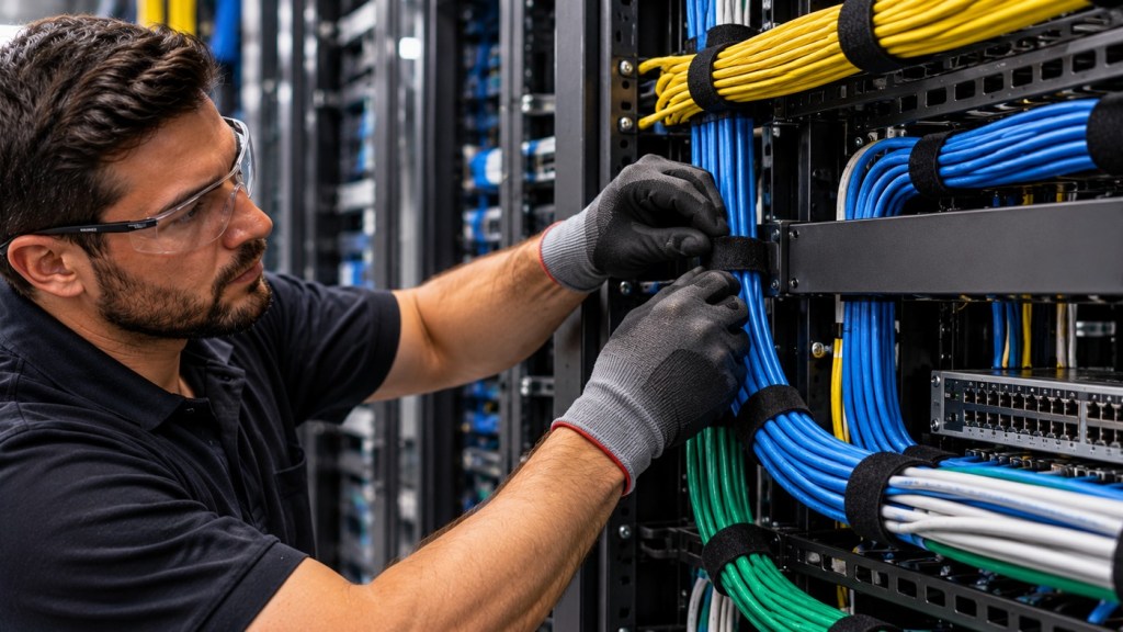
Mechanical damage does not end when the pulling rope comes off. Tight cable ties, unsupported vertical runs, undersized service loops, sharp rack edges, crushed bundles, and poor strain relief can continue applying stress for years.
Use hook-and-loop where appropriate, support long vertical runs, preserve the correct bend radius, protect connector exits, and leave service loops large enough to satisfy the cable specification. Good rack-and-stack workmanship is not just visual organization. It is mechanical protection for the physical layer.
The Rule Is Simple Even When the Math Is Not
Before a serious cable pull, know four numbers: maximum pulling tension, minimum bend radius under tension, maximum allowable sidewall pressure when applicable, and the pathway geometry.
Then build the pull around those limits instead of discovering them after the cable is installed.
A network can recover from a bad switch configuration. A damaged cable buried behind walls, under a slab, or inside a crowded conduit is much harder to forgive.


Leave a comment