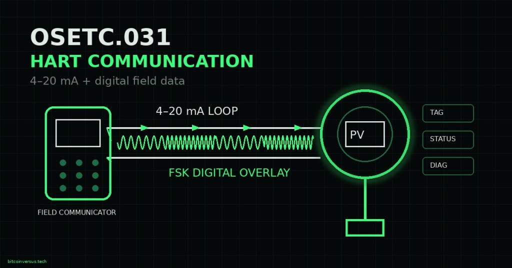
Elementary overview: HART stands for Highway Addressable Remote Transducer. It lets a smart field instrument keep using the familiar 4–20 mA current loop for its primary process value while adding two-way digital communication on the same wiring. That means a pressure, level, flow, or temperature transmitter can still send the analog value a PLC or DCS expects while a technician also reads device identity, configuration, status, diagnostics, and additional variables. FieldComm Group describes HART as a bidirectional protocol that provides simultaneous analog and digital communication between intelligent field instruments and host systems.
One Pair of Wires Carries Two Channels
In a conventional point-to-point HART loop, the analog channel remains the 4–20 mA signal that represents the primary variable. The digital channel is superimposed on that same loop. This is why HART did not require plants to abandon existing analog instrumentation wiring just to gain digital access. It extends the same installed loop with device information that a basic analog current alone cannot carry. That makes HART a natural continuation of process transmitter calibration: after confirming the analog output, a technician can also interrogate the device digitally.
FSK Is the Digital Signal Riding on the Loop
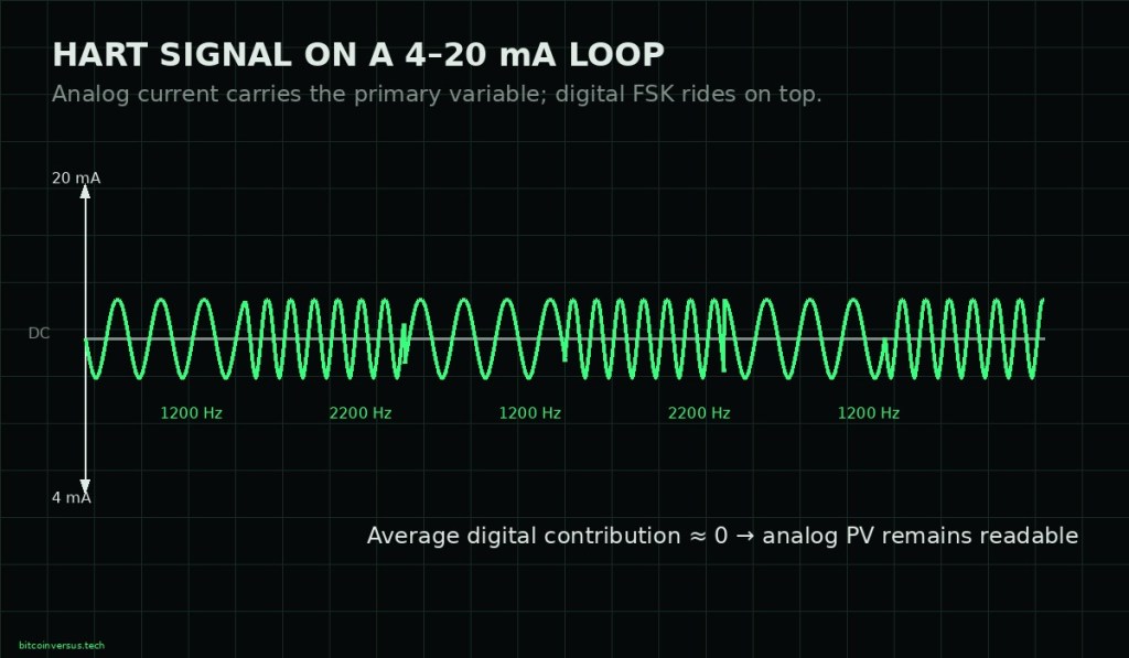
Traditional wired HART uses frequency-shift keying, or FSK, based on the Bell 202 signaling method. FieldComm Group states that the digital signal uses two audio frequencies and communicates at 1200 bits per second. Because that AC digital component is designed so its average contribution does not shift the DC process current, the controller can continue reading the analog 4–20 mA value while the host exchanges digital messages. This is fundamentally different from a pure 0–10 V analog signal, which does not inherently include a digital protocol layer.
Where the Field Communicator Connects
A handheld HART communicator or compatible modem connects across the loop so it can detect and inject the digital HART signal without becoming the series current-measuring element. The loop must provide adequate impedance for reliable HART communication; a 250 Ω load is common in training diagrams and many conventional installations, but the correct minimum and maximum loop resistance must come from the specific transmitter, power-supply, barrier, and control-system documentation. Before attaching test equipment in a live process, follow the approved work permit and energy-isolation procedure where required.
What a Technician Can Read or Change
Once communication is established, a HART host can typically identify the instrument and read parameters such as tag, range values, process variables, device status, and diagnostics. Depending on the device and permissions, it can also support configuration, loop tests, reranging, and calibration-related functions. Those functions must not be confused with one another: as covered in OSETC.030, reranging changes configured LRV/URV, while sensor trim and analog output trim correct different parts of the measurement chain. HART gives the technician digital access to those functions; it does not make every adjustment appropriate.
Basic HART Troubleshooting
When the analog loop looks normal but the communicator cannot see the device, troubleshoot the communication path rather than immediately blaming the transmitter. Verify that the instrument actually supports HART, confirm loop power and polarity, check that the communicator is connected across the loop, confirm adequate loop resistance, inspect barriers or isolators for HART compatibility, and verify that wiring capacitance, shorts, loose terminations, or excessive electrical noise are not attenuating the FSK signal. A loop test can then help separate the field device from the analog input and control-system indication.
Field Checklist
- Confirm the transmitter nameplate or datasheet explicitly supports HART.
- Verify loop supply voltage and polarity.
- Confirm the analog 4–20 mA value is reasonable before changing configuration.
- Connect the communicator across the loop, not in series as an ammeter.
- Verify adequate loop impedance using the device and host documentation.
- Read the device tag, range, units, status, and diagnostics before making changes.
- Record the original configuration before reranging or trimming.
- Use a loop test to verify the PLC/DCS or analog input when needed.
- Restore the loop and confirm the control-system indication after maintenance.
Exercises
- Explain why the HART digital signal can coexist with a 4–20 mA analog value on the same pair of wires.
- Describe the difference between the analog primary variable and the digital HART information.
- Draw a basic point-to-point loop with power supply, transmitter, load, analog input, and HART communicator.
- Explain why a communicator should normally connect across the loop rather than in series.
- List four reasons a communicator may fail to detect a HART transmitter even when the 4–20 mA signal is present.
- Explain why reranging a transmitter is not the same as calibrating its sensor.
Knowledge Check + Answers
- What does HART stand for? Highway Addressable Remote Transducer.
- What normally carries the primary process value in a conventional wired HART loop? The 4–20 mA analog current.
- What technique carries the digital information? Frequency-shift keying, or FSK.
- What is the traditional wired HART data rate? 1200 bits per second.
- Does HART replace the 4–20 mA signal in a normal point-to-point loop? No. It adds digital communication on top of it.
- Name three types of digital information HART can provide. Examples include device identification, configuration, diagnostics, status, and additional process variables.
- Is 250 Ω mandatory for every HART installation? No. It is a common conventional value; use the actual device and host loop-resistance requirements.
Primary Technical References
Next Lesson
Next in the Electrical Technician track: OSETC.032 — HART Loop Tests and Device Diagnostics. That lesson will stay focused on practical test modes, status information, and isolating field-device problems from PLC/DCS input problems rather than repeating HART fundamentals.
BitcoinVersus.Tech
Editor’s Note: This lesson is educational and should be used alongside the instrument manufacturer’s documentation, site procedures, and approved safety practices.
We volunteer daily to improve the credibility of the information on this platform. If you would like to support the research, please donate here: 3C9o19EH5HSiwEPyCTmEKzxhNCbo2X6TTb
BitcoinVersus.tech is not a financial advisor. This media platform reports on technical and financial subjects purely for informational purposes.


Leave a comment