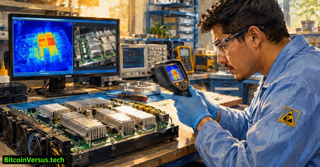
OSHRE.010 explains how thermal imaging can assist technicians diagnosing Bitcoin mining ASIC hashboards without confusing an apparent hotspot with a proven component failure. An infrared camera reveals patterns of surface radiation. It cannot identify a defective chip by itself, see through aluminum heatsinks or replace electrical measurements. The most reliable interpretation combines comparable operating conditions, calibrated settings, maintenance records and corroborating tests.
What the infrared camera measures
An infrared imager senses emitted and reflected radiation, then estimates surface temperature using settings for emissivity and environmental conditions. The image palette assigns visible colors to the measurements; bright yellow or red pixels are not inherently above a safe temperature. A changing automatic scale can make two otherwise similar images look dramatically different. FLIR’s emissivity guide explains the basic measurement limitation.
On an ASIC board, the camera may image heatsinks, encapsulation, solder mask, connectors, exposed metal and surrounding structures. A heat signature on a heatsink reflects a complex path from the silicon junction through interfaces and into moving air. It does not directly establish an individual ASIC’s internal junction temperature. OSHRE.004 separately explains embedded temperature sensing and thermal protection.
Emissivity, reflections and spatial resolution
Different materials emit infrared energy differently. FLIR recommends an emissivity setting around 0.9 for plastics in a general PCB context, while describing a much lower value around 0.15 for some metal surfaces, depending on coating and condition. Neither value is a universal setting for every board. Reflective metals can mirror nearby warm objects; incorrect assumptions produce misleading temperature estimates. The manufacturer’s PCB-specific note makes the distinction explicit.
Camera pixels also average radiation from a finite area. A tiny resistor or solder joint occupying only part of a pixel may appear cooler than its true surface temperature. Distance, focus and lens choice therefore matter. FLIR’s imaging guidance advises checking target size and reflections and avoiding dangerous proximity to live components.
Compare equivalent regions, not arbitrary colors
A useful diagnostic comparison requires the same board revision, known load, airflow direction, fan state, ambient temperature, camera position and stable imaging scale. A 60°C spot on one board may be normal while a 45°C spot elsewhere may warrant investigation. Refer to OSHRE.008 for electrical baseline methods and OSHRE.006 for visual solder-joint evidence.
Consider an invented training sample: four equivalent points show apparent temperatures of 50°C, 51°C, 52°C and 68°C. Their median is 51.5°C, and the highest point exceeds it by 16.5°C. The calculation identifies an outlier, not a manufacturer alarm threshold or proof of a short circuit. Different emissivity, local airflow and legitimate loading could also explain the difference.
A disciplined, safety-first workflow
First, identify the miner, board revision, firmware, operating mode and previously recorded symptoms. Second, review permitted controller temperature readings and error logs. Third, under approved procedures, acquire comparable thermal images and preserve the scale, emissivity and camera position. Fourth, flag regional differences for additional examination. Fifth, after proper shutdown, isolation and discharge verification, inspect suspected connectors or joints; use OSHRE.009 on diode-mode limitations when appropriate.
Do not remove protective covers, touch energized circuits, change firmware power limits or inject test voltage merely to create heat. Miner power systems can contain hazardous voltages and stored energy. Follow the site’s lockout and electrical safety process; active-board examination belongs to trained, authorized personnel using suitable equipment.
What thermal evidence can and cannot establish
Thermography can help prioritize investigation of abnormal heat patterns, poor thermal contact, cooling obstruction or suspect power stages. It cannot, alone, distinguish an overheated but healthy component from an internally failed one. OSHRE.003 covers complementary chain diagnostics. Learning conclusion: treat every thermal image as a measurement conditioned by surface physics, camera settings and operating state—not as an automatic repair verdict.


Leave a Reply