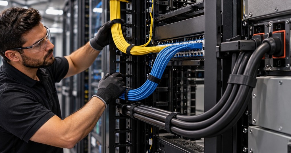
Cable bend radius does not have one universal number. A bend that is perfectly acceptable for one cable can be too tight for another cable that looks almost the same from across the room.
That matters in data centers, telecom rooms, industrial plants, semiconductor facilities, and Bitcoin mining sites because the same pathway can contain fiber optic cable, Ethernet cable, control wiring, and heavy electrical power cable. Each cable family is built differently and can fail differently.
BitcoinVersus.Tech already published a general cable bend radius explainer. This follow-up answers the more useful field question: why can’t technicians just memorize one bend-radius rule and use it everywhere?
Start With the Basic Geometry
The bend radius is the radius of the curve a cable follows as it turns. Bend diameter is twice the radius. That sounds elementary, but confusing radius and diameter can create a two-to-one installation error when technicians select pulleys, sheaves, service loops, raceways, or cable-management hardware.
The common shorthand looks like this:
Minimum bend radius = cable outside diameter × required bend factor
The important part is the bend factor. It changes with cable construction and sometimes changes again depending on whether the cable is being pulled or is already resting in its final installed position.
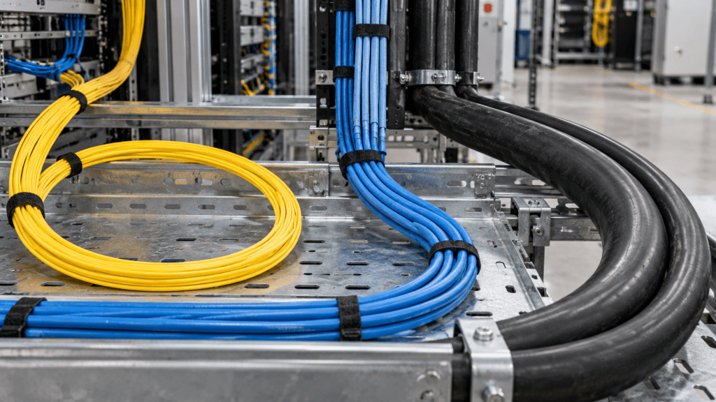
Fiber Often Uses 10× Installed and 20× During Pulling
The familiar fiber rule is 10 times the cable diameter after installation and 20 times the cable diameter while the cable is under pulling tension. The Fiber Optic Association uses that as its normal recommendation while repeatedly warning installers to check the actual manufacturer specification because some fiber designs use different values.
For a 6 mm fiber cable, a 10× installed rule would mean a 60 mm minimum bend radius. Under a 20× pulling rule, the radius becomes 120 mm. If the technician is choosing a pulley or storage loop by diameter instead of radius, that number doubles again.
Why so much caution? Tight bends can create macrobending loss, where optical power escapes the guided path because the fiber is curved too aggressively. Extreme stress can also kink buffer tubes, damage the cable structure, or reduce long-term reliability. That is why bend control belongs beside fiber handling, optical power measurement, and OTDR testing as a basic fiber-technician skill.
Bend-Insensitive Fiber Changes the Visual Test
Modern bend-insensitive single-mode fiber is the reason technicians should be careful about declaring a bend “wrong” by sight alone. Some specialty fibers are designed to tolerate dramatically smaller radii than conventional outside-plant cable. A tight-looking loop can therefore be legal for one product and damaging for another.
The lesson is simple: identify the exact cable before applying a generic multiplier. Jacket markings, part numbers, construction drawings, and manufacturer data sheets are stronger evidence than a visual guess.
Cat 6 Ethernet Can Be Much Tighter Than Fiber
For many horizontal twisted-pair cables, the bend factor is smaller. A current CommScope Category 6 cable lists a minimum bend radius of four times the outside cable diameter. Its nominal jacket diameter is 5.41 mm, so 4× gives roughly 21.6 mm, or about 0.85 inch.
That does not mean Ethernet can be folded sharply around a rack post. Twisted-pair performance depends on controlled conductor geometry. Crushing, kinking, over-tight cable ties, or aggressive bends can disturb the pair relationship and create performance problems. Proper structured cabling therefore treats bend radius as part of the same workmanship discipline as termination, labeling, pathway routing, strain relief, and testing.
The distinction also matters for RJ45 terminations, Cat5e versus Cat 6, and Power over Ethernet. A cable may still establish a link after poor handling while no longer delivering the margin expected from a properly installed channel.
Power Cable Can Jump From 4× to 12× or More
This is where the “one rule for every cable” idea really falls apart. Power-cable bend requirements depend on conductor size, insulation system, shielding, armor, voltage class, cable assembly, and installation method.
Southwire’s bend-radius guidance shows why. Its tables use different multipliers for different cable designs. Some 600 V to 2 kV constructions use factors around 4× to 7× outside diameter, while several 5 kV to 35 kV shielded cable constructions use factors of 8× or 12×.
A current Southwire 15 kV example with an outside diameter near 0.986 inch specifies an 11.8-inch minimum bend radius—almost exactly 12× the cable diameter. That is radically different from the roughly 4× value seen in the CommScope Cat 6 example even though both rules are still expressed as a multiple of outside diameter.
Heavy cable also introduces another problem: sidewall pressure while pulling through bends. A cable can remain above its theoretical minimum radius and still be damaged if pulling tension forces it too hard against a sheave, conduit bend, or tray transition. That connects bend radius directly to electrical distribution equipment, busway, and the physical pathways feeding racks and equipment.
Why Pulling Tension Changes the Rule
A cable sitting gently in a tray is not experiencing the same mechanical forces as a cable being dragged through conduit. During a pull, tension acts along the cable while the bend pushes that cable sideways against the pathway or pulley. The tighter the turn and the greater the pulling force, the higher the mechanical stress.
That is why installers should think about bend radius, pulling tension, sidewall pressure, and crush resistance together. They are separate specifications, but the installation can violate several of them at the same physical corner.
Service Loops Need Radius Too
Technicians often remember bend radius at rack corners and forget it when storing slack. A service loop is still a bend. If a cable needs a 60 mm minimum bend radius, coiling the spare cable into a tiny loop can defeat all the careful routing that came before it.
This is especially important around fiber patch cords, patch panels, splice trays, overhead baskets, vertical managers, and the rear of dense racks. The cleanest-looking cable bundle is not automatically the healthiest one if the loops are too small or the hook-and-loop straps are crushing the jacket.
Five Bend-Radius Mistakes Technicians Keep Making
- Using one multiplier for every cable. Fiber, copper data cable, coax, control cable, and power cable can all have different limits.
- Confusing radius with diameter. A 100 mm radius means a 200 mm diameter loop.
- Ignoring the installation condition. A cable under pulling tension may require a larger radius than the same cable after installation.
- Bending around hardware edges. Rack rails, tray lips, enclosure knockouts, and conduit entries can create a sharp local bend even when the overall route looks clean.
- Assuming “the link came up” means the cable is fine. Fiber can gain loss and Ethernet can lose performance margin without becoming completely dead.
How to Verify the Installation
First, identify the cable and read its data sheet. Then inspect every transition: tray drops, vertical managers, rack entries, patch panels, service loops, conduit sweeps, splice enclosures, and equipment connections. Look for kinks, flattened jackets, sharp corners, over-tight ties, or loops smaller than the specified radius.
For fiber, optical loss testing and OTDR can help identify abnormal loss and fault locations. For copper Ethernet, a proper cable-certification tester can verify the installed channel against the required category performance. For power cable, use the project’s approved inspection, commissioning, and electrical test procedure rather than inventing a generic field test.
The Rule That Actually Works Everywhere
The safest universal bend-radius rule is not 4×, 10×, 12×, or 20×.
The universal rule is: identify the exact cable, find the manufacturer’s minimum bend radius for the actual installation condition, then route the cable with margin instead of treating the minimum as a target.
That one habit scales from a single Cat 6 run to dense rack-and-stack environments, fiber backbones, medium-voltage feeders, and entire data-center campuses. Good cable management is not cosmetic. It is physical-layer reliability.


Leave a comment