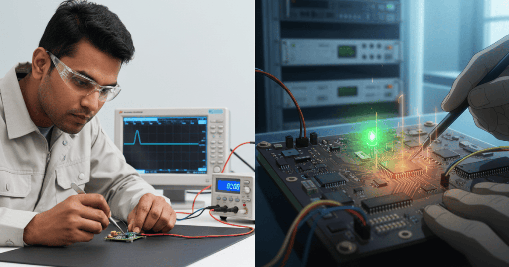
Brownout reset diagnostics is the practice of determining whether a microcontroller rebooted because its power-supply voltage fell below a device-defined safe threshold. In embedded systems, a brief voltage dip can look like a firmware crash, a watchdog fault, or an intermittent communication failure. The distinguishing evidence comes from the actual voltage waveform, the chip’s reset-cause status, the power-system design, and the circumstances under which the reset repeats. This Firmware Technician course entry is cataloged internally as OSFTC.015. It follows MCUboot upgrade recovery validation and builds upon firmware crash logs. Its main purpose is to prevent technicians from re-flashing otherwise healthy firmware when the board really has an electrical supply problem.
Elementary overview
A microcontroller is a small computer built onto a chip. Like a laptop, it must receive electrical power within an allowed range. If the voltage drops too far while code is running, the CPU, memory and peripherals may stop meeting their electrical specifications. A brownout detector (BOD) or brownout reset (BOR) circuit watches the supply and, when enabled and correctly configured, keeps the chip in reset until the voltage recovers. Think of it as an automatic safety stop for a machine that no longer has enough power to run predictably. It does not repair a weak regulator, connector or battery; it prevents operation under some invalid conditions.
A technician should first establish the exact microcontroller family, board revision, operating frequency, supply arrangement and allowed power range. Brownout thresholds, filtering, reset behavior and flag names are device-specific. A level quoted for one STM32 or AVR must never be assumed correct for another. Microchip’s brownout application note explains the relationship between voltage, CPU frequency and safe code execution, while STMicroelectronics’ supply-design guidance covers power-on and brownout supervision.
Reset sources that look similar
- Power-on reset (POR): the chip is entering a powered state, typically after its supply was removed or first applied. It may have a different voltage limit and flag from BOR.
- Brownout reset (BOR/BOD): the monitored rail crossed a configured low-voltage threshold for a sufficient duration. Availability and configuration depend on the device.
- Watchdog reset: a watchdog timer expired because the program did not satisfy its configured service conditions. Power instability can sometimes cause a software stall that later triggers a watchdog, so a watchdog flag alone does not establish the root cause.
- External reset: a reset pin or supervisor asserted the chip’s reset input, including when an external voltage-monitoring IC acts.
- Software reset: firmware deliberately requested a restart. The application may record why it requested that action.
- Fault-driven reset: device-specific lockup, protection, or security mechanisms restarted the core. The exact distinction requires the reference manual.
Multiple reset indications can coexist, and some flags remain latched until software clears them. A reset register is evidence, not a complete diagnosis. Record it before clearing; correlate it with a measured voltage trace and recent device activity.
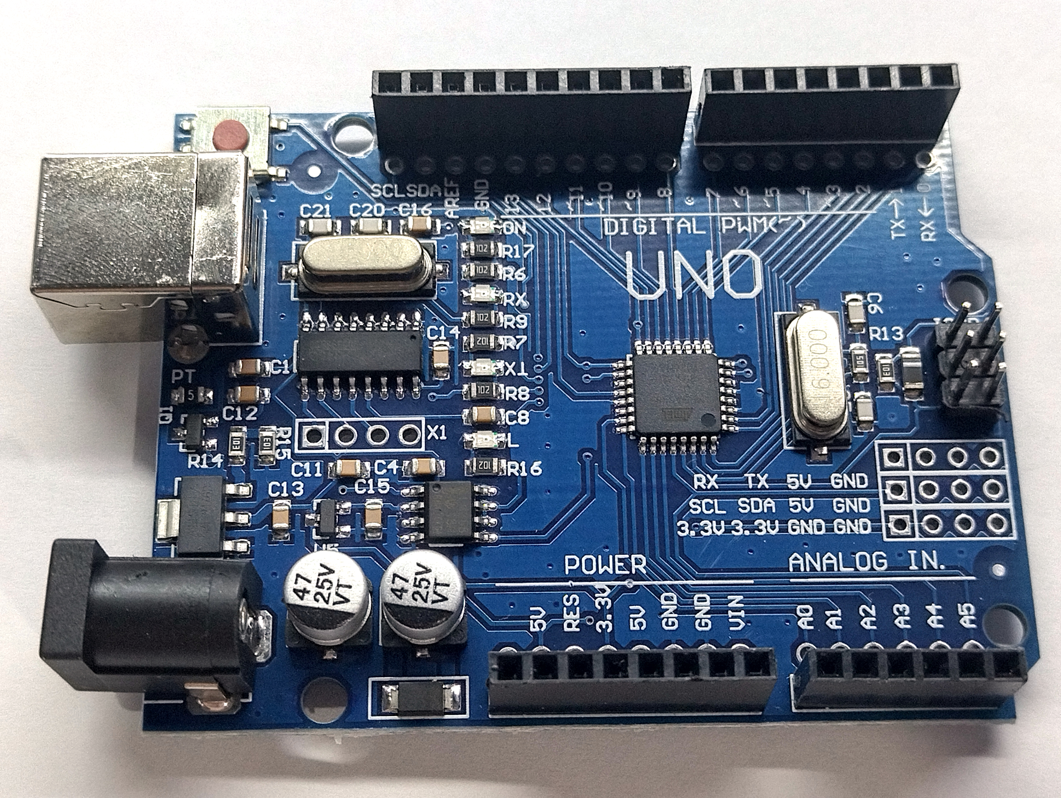
Related external video: Microchip — AVR Insights, Episode 19: Brown Out Detector, a manufacturer tutorial on brownout reset detection. The video opens on Microchip’s official website because the site’s native YouTube player is not rendering.
The Microchip tutorial explains why an AVR device must be protected from low supply voltage and how its brownout detector holds the MCU in reset. The technician’s next step is to verify the specific device and which reset flags survive its startup sequence. Recording only “it rebooted” loses the most useful forensic information.
How low supply voltage causes a reboot
Suppose a board normally operates from a 3.3 V rail. Its CPU, flash memory and peripherals have published voltage limits, often related to clock speed and temperature. A wireless transmitter, motor driver, storage write or peripheral startup can draw a short burst of current. If the regulator responds poorly, the cable has excessive resistance, the battery is depleted or a solder joint is defective, the supply at the microcontroller can sag. The chip may reset if the brownout monitor sees its programmed threshold crossed. Microchip’s August 2026 troubleshooting guidance identifies regulators, power-sequencing issues, inrush current, batteries and soldering faults as plausible startup-reset causes.
A reset threshold is not a universal minimum operating voltage. A useful design must consider the supply-voltage requirement for the chosen clock frequency, oscillator, flash operations, peripherals and expected temperature. The detector’s accuracy, hysteresis and response time also matter. A very short spike may be rejected by the detector, or may be missed by a slow logging system; an oscilloscope helps reveal events that ordinary telemetry averages away.
The brownout detector, voltage monitor and reset flag
A brownout detector usually compares a supply rail with a reference voltage. Some devices offer programmable levels, while others have fixed or fuse-selected settings. Hysteresis introduces separate falling and rising thresholds so the chip does not repeatedly switch states when its voltage hovers near one level. Microchip documents note that detection may require the voltage to remain below threshold for a specified time. Board technicians must check the part’s datasheet rather than treating a brownout threshold like an instantaneous, ideal switch.
Some STM32 families also provide a programmable voltage detector (PVD) that can generate an early-warning interrupt before the core reaches a reset threshold. PVD is not necessarily the same as BOR: it may report the warning without resetting the chip, and it depends on the software and power architecture. Some MCU families expose POR, BOR, watchdog and other reset causes in register flags such as an RCC reset-status register; names and clear semantics vary by family. ST’s STM32 power supply note describes both voltage monitoring and the retention of reset status for post-reboot analysis.
A safe bench diagnostic workflow
- Identify the board: record device model, board revision, regulator topology, supply ratings, peripheral loads, installed firmware and the service complaint.
- Preserve evidence: save boot logs, timestamped resets, fault counters and reset-cause bits before diagnostic firmware or a debugger clears them. Keep the configuration and firmware image unchanged at first.
- Check simple power faults: with appropriate authorized procedures, inspect connector seating, supply limits, corrosion, regulator heating and known battery condition. Never improvise probes around hazardous mains voltage.
- Measure at the chip rail: on a safe low-voltage test board, use an appropriately rated and grounded oscilloscope with a short ground connection at an approved test point near the MCU supply; compare measured power with the datasheet requirements.
- Trigger the capture: set the scope to catch a rail dip or observe the power rail together with reset or a known event signal. Use adequate bandwidth and sampling rate for the suspected transient.
- Correlate conditions: note whether resets occur during a radio burst, motor startup, flash write, high clock mode or peripheral enable. Repeat only permitted tests without risking stored data or live equipment.
- Isolate the cause: compare a known-good supply, cable or permitted peripheral state with the suspect configuration. Evaluate regulator transient response, inrush, decoupling and the PCB power path.
- Document recovery: retain the waveform, trigger settings, reset flags, firmware build, supply parameters and a repeatable result. Escalate design or component replacement issues through change control.
A digital multimeter is useful for steady voltage but may not capture a microsecond- or millisecond-scale droop. An oscilloscope is often the decisive instrument; measuring only at the bench supply’s terminals can miss voltage lost along the cable, PCB trace, protection device or connector. See ST’s STM32 debug-toolbox application note for hardware-assisted diagnosis.
Practical scenario: a controller resets when its radio transmits
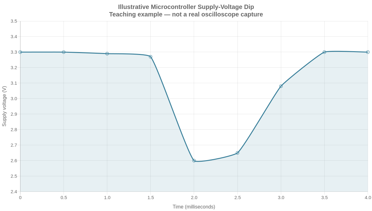
An industrial sensor node runs normally for minutes, then restarts whenever its radio sends a high-power packet. The firmware log shows repeated boots but no captured application exception. A technician measures a stable 3.3 V at idle, then uses the oscilloscope to capture an illustrative dip to 2.6 V at the MCU VDD pin during radio startup. The brownout threshold and operating minimum must be taken from the specific device documentation; a 2.6 V sample reading alone does not prove that BOR triggered.
The team compares the captured waveform with the approved supply design and the MCU reset flags. If the flags agree with an undervoltage event, the likely investigation shifts from firmware flashing to battery internal resistance, regulator current capacity, power distribution and local decoupling. If the reset is actually watchdog-induced, investigate whether the power dip first disrupted code execution or whether an unrelated scheduling issue occurred. A responsible repair log separates observed facts, working hypotheses and confirmed cause.
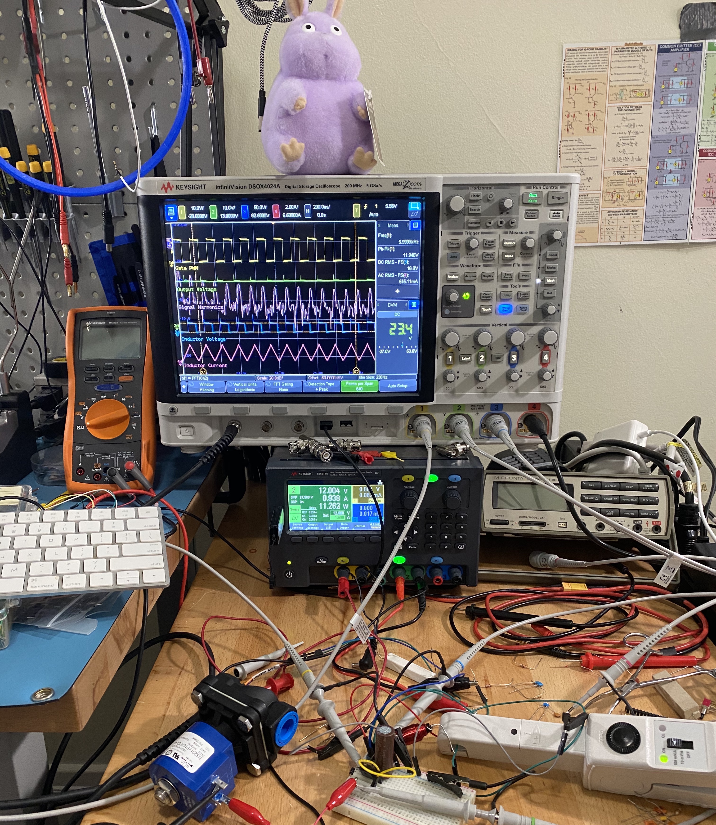
Related external video: element14 presents — How to Measure Ripple Voltage on a Switch-Mode Supply, an English-language oscilloscope tutorial. Watch on YouTube; in-page YouTube playback is not confirmed on this site.
The element14 video demonstrates how an oscilloscope reveals power-supply ripple and noise that a multimeter can miss. Consult the installed microcontroller’s reference manual for BOR status and voltage limits.
Practical scenario: the system loops during startup
Consider a controller that reaches its boot logo but reboots as a motor driver initializes. If startup current briefly overwhelms the regulator, the resulting supply dip may repeatedly assert BOR, preventing application startup. If the brownout monitor is disabled, low supply voltage may instead produce erratic software execution, corrupted peripheral state or a later watchdog reset. In neither case does a repeated boot logo automatically establish a firmware defect.
The technician first confirms that the motor and PCB test setup are electrically safe, then captures VDD and reset timing during a permitted startup test. If the rail drops when the motor-driver supply is enabled, document inrush, return-path integrity and supply stability. Avoid indiscriminately increasing capacitance: excessive bulk capacitance can change startup ramp time or power sequencing. Microchip explicitly warns that both undersized and poorly configured supply networks can contribute to resets.
What not to do
- Do not disable brownout protection merely to keep a failing device running. That may permit out-of-specification code execution and jeopardize nonvolatile data.
- Do not change eFuse, option-byte or safety settings without documented authorization and a validated recovery path. Some changes are irreversible or board-dependent.
- Do not assume an oscilloscope probe ground is electrically isolated. Use the correct safe measurement architecture for the device and follow lab electrical-safety procedures.
- Do not erase reset flags or reflash firmware before capturing evidence. A “fixed by reinstalling” result may only reset the diagnostic state.
- Do not infer the BOR threshold from the nominal board supply voltage. Verify thresholds, tolerance, time filtering and hysteresis in the exact part datasheet.
Knowledge check
- Why might a voltmeter report a stable 3.3 V supply while an MCU repeatedly restarts under load?
- What is the diagnostic difference between a brownout-reset flag and a time-correlated oscilloscope capture?
- Why can a watchdog reset flag appear even when the electrical power system caused the original failure?
- How does hysteresis help prevent an unstable supply from rapidly toggling reset state?
- Which evidence must be preserved before clearing reset-cause registers or updating firmware?
Answers: A voltmeter may average away brief supply transients; a scope can capture the waveform. A reset flag records a reset mechanism supported by the device, while a synchronized voltage trace reveals what the rail actually did. An undervoltage event can make software hang until the watchdog expires. Hysteresis provides different reset-assert and release thresholds. Preserve firmware version, board identity, current reset status, logs, timestamps, rail measurements and instrument settings.
Elementary conclusion
Brownout reset diagnostics begins with a simple distinction: the microcontroller’s software may be functioning normally, but its electrical supply may not be. The BOD/BOR circuit is a safeguard against operation at inadequate voltage, not a cure for the source of the voltage loss. Good technicians combine datasheets, reset flags and waveform measurements to identify the difference between true power failure, watchdog expiration and other restart causes. They then repair or escalate the power path rather than blindly rewriting firmware.
Primary references and related lessons
Manufacturer references: Microchip AN2747 — Brown-out Detector; Microchip — Devices Reset During Current Changes; STMicroelectronics — MCU Power Supply Design; STMicroelectronics — Reset and Voltage Monitoring. Continue with Watchdog Timers and Reset Loops, Firmware Crash Logs, Read-Only eFuse and Option-Byte Audits and MCUboot Recovery Validation.
BitcoinVersus.Tech Editor’s Note: We volunteer daily to ensure the credibility of the information on this platform is Verifiably True. If you would like to support our independent technical education and research, please scan the QR code below to donate 5,000 sats (best results on a laptop or larger screen).
For mobile scanning, open this lesson on a laptop or larger screen and scan the QR code with a compatible Bitcoin wallet on your phone. Confirm the destination address before sending: 3C9o19EH5HSiwEPyCTmEKzxhNCbo2X6TTb.
BitcoinVersus.tech is not a financial advisor. This media platform reports on financial subjects purely for informational purposes.


Leave a Reply