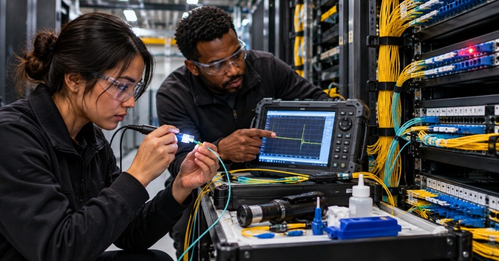
Elementary Overview
Fiber troubleshooting is the process of turning an optical symptom into a proven physical cause. Restoration is the controlled work that returns the link to service and verifies that the repair actually meets the required optical and network performance.
This lesson follows OSFOTC.007: Fiber Cable Installation and Routing. The earlier modules taught individual tools and procedures. OSFOTC.008 combines them into one field workflow for outages, intermittent loss, high attenuation, damaged cable, bad connectors, polarity problems, and post-repair acceptance.
A technician should not begin by replacing random parts. Start with the symptom, protect the evidence, work from the simplest likely causes toward more invasive repairs, and document what changed.
Start With Safety And Scope
Before disconnecting anything, identify the affected service, fibers, panels, transceivers, maintenance window, and restoration authority. Apply the handling rules from OSFOTC.001: Fiber Optic Safety, Handling, Inspection, and Cleaning Basics. Never look into a fiber or optical port. Active communications wavelengths may be invisible to the eye.
Record the original state before moving patch cords. In a dense panel, one accidental move can create a second outage and destroy the evidence needed to understand the first one.
Define The Symptom Before Choosing The Tool
Different symptoms suggest different first tests. A completely dead link may point toward loss of optical power, wrong polarity, a disconnected patch, a severe break, or a failed optic. A link with intermittent errors may suggest contamination, marginal receive power, microbending, a stressed connector, or a transceiver problem. A link that failed immediately after construction should raise questions about polarity, connector cleanliness, splice quality, bend radius, and patching.
If the Ethernet or storage interface is involved, correlate the optical work with the host-side checks from OSDCTC.008: Server Network Configuration and Validation. A physical fiber problem and a logical VLAN or LACP problem can produce similar “link down” symptoms at the application layer.
Inspect Before You Clean
Connector contamination is one of the first things to eliminate because it is common, fast to test, and capable of causing both insertion loss and reflectance. Fluke Networks’ fiber inspection guidance describes contaminated end faces as a leading cause of fiber-related problems and emphasizes inspecting before connection, cleaning only when necessary, and inspecting again after cleaning.
Inspect both mating surfaces when possible: the patch-cord end face and the bulkhead or equipment port. A clean jumper can be contaminated immediately by a dirty port. Dust caps do not prove cleanliness.
Fluke Networks — connector cleaning and inspection practices, including why technicians should inspect before and after cleaning.
Verify Optical Power Before Assuming The Cable Is Broken
Use the measurement discipline from OSFOTC.002: Optical Power Meter Basics. Confirm the correct wavelength, reference method, known-good test cords, and whether you are measuring a live transmitter or performing insertion-loss testing with a controlled source.
Compare measured receive power with the supported range of the actual transceiver. A reading of −8 dBm is not universally good or bad. The answer depends on the optic’s transmitter range, receiver sensitivity, overload limit, wavelength, fiber type, and link design. Use the engineering method from OSFOEC.001: Optical Link Budget Engineering when deciding whether the measured loss is plausible.
Check Polarity And Patch Mapping Early
A perfectly clean, low-loss fiber still fails if transmit is connected to transmit or receive is connected to receive. Recheck the connector and polarity rules from OSFOTC.004: Fiber Connector Types and Polarity.
For duplex LC links, verify Tx-to-Rx mapping end to end. For MPO/MTP systems, confirm the designed polarity method, cassette orientation, keying, pinning, and whether the channel is Base-8, Base-12, Base-16, or another approved architecture. Do not “fix” an MPO polarity problem by randomly flipping components until link lights appear.
Use A VFL For Continuity, Identification, And Visible Faults
A visual fault locator sends visible red light into the fiber. It is useful for identifying a fiber, verifying continuity and polarity, and finding some breaks, bad splices, or severe bends where light leaks from the cable. It is especially useful for short links and faults that fall inside an OTDR dead zone.
A VFL is not an optical loss meter and it does not certify link performance. Seeing red light at the far end proves continuity, not acceptable attenuation.
Use The OTDR To Locate The Fault
When the loss exists somewhere inside the cable plant, move to the method from OSFOTC.003: OTDR Field Testing. An OTDR measures backscatter and reflections so the technician can estimate where connectors, splices, bends, breaks, and the end of the fiber are located.
Fluke Networks’ OTDR troubleshooting guide notes that an OTDR can identify individual high-loss events, bends, breaks, and bad connections that a total insertion-loss measurement cannot localize. It also recommends comparing wavelengths when looking for stressed fiber because bend loss can increase more strongly at the longer wavelength.
Use launch and receive fibers when the test objective requires characterization of the near-end and far-end connectors. Choose range, pulse width, averaging, event thresholds, and index of refraction appropriately. An automatic trace is useful, but the technician still needs to interpret whether an event matches the physical cable plant.
Field example — using OTDR distance information and a VFL together to locate fibers and faults in a real plant.
Distinguish A Bend From A Break
A severe break often creates a large reflective event followed by the end of usable backscatter. A bend may create a nonreflective loss event while the trace continues afterward. A connector can produce both loss and reflection. A fusion splice is normally nonreflective and should have low loss when properly made.
Do not identify an event from the trace alone when the physical layout is available. Compare OTDR distance with cable markers, splice closures, patch panels, handholes, vaults, trays, and known service loops. Revisit the routing rules from OSFOTC.007 when the event appears near a bend, tray transition, cabinet entry, or strain point.
Compare Two Wavelengths When Stress Is Suspected
A useful troubleshooting technique is to compare OTDR behavior at two supported wavelengths. A macrobend often shows a larger loss increase at the longer wavelength. For example, single-mode troubleshooting commonly compares 1310 nm and 1550 nm, while multimode testing commonly uses 850 nm and 1300 nm. The exact procedure and acceptance limit depend on the cable, test standard, and application.
This comparison helps separate a stressed bend from an ordinary splice or connector event, but it does not replace physical inspection.
Check For Fiber-Type And Transceiver Mismatch
A troubleshooting workflow must also confirm that the installed optics and fiber actually belong together. Review the selection rules from OSFOEC.003: Optical Transceiver Selection Engineering. Mixing single-mode and multimode components, using the wrong wavelength, exceeding supported reach, or using an unsupported breakout can produce loss or link behavior that looks like a cable fault.
Verify both ends: optic form factor, data rate, lane count, wavelength, fiber type, connector interface, encoding or FEC requirements where relevant, and vendor support rules.
When A Splice Is The Fault, Repair It Deliberately
If the evidence points to a failed splice or damaged cable section, use the process from OSFOTC.006: Fiber Fusion Splicing. Identify the exact fibers, preserve sufficient slack, prepare the work area, strip, clean, cleave, splice, protect, route, and then test.
Do not accept a splice merely because the fusion splicer reports a low estimated loss. The repair must be verified optically from the cable plant. OTDR testing can characterize the event; insertion-loss testing verifies the end-to-end channel loss.
Fiber Optic Association — restoration lecture focused on finding fiber problems and making repairs efficiently.
Restoration Should Be Planned Before The Outage
The Fiber Optic Association’s technical reference includes dedicated material on troubleshooting and fiber restoration. The central operational lesson is simple: restoration is much faster when documentation, spare cable, compatible closures, pigtails, splice sleeves, cleaning supplies, launch fibers, test equipment, and access procedures already exist before the failure.
A restoration kit should match the actual plant. Having spare LC jumpers does not help if the emergency repair requires an MPO trunk, outdoor loose-tube cable, a specific splice closure, or enough single-mode cable to bypass a damaged route.
Real Fiber Cuts Become Real Outages
Outside plant damage, construction activity, digging, vehicle impact, fire, water, rodents, and building work can all turn a healthy fiber route into an outage. Service-provider incident notices are useful reminders that a “network outage” can have a very physical cause.
Sparklight — a real 2026 outage notice attributing service disruption to a third-party fiber cut.
High-Speed Data Centers Make Optical Discipline More Important
Data centers continue to push more traffic onto optical interconnects, which means contamination, bend loss, bad polarity, damaged trunks, and weak restoration procedures affect increasingly important links. The network-fabric context in OSDCEC.009: Data Center Network Fabrics explains why those fiber paths are part of larger redundant systems rather than isolated cables.
Industry discussion — the continuing shift toward optical interconnects in AI data centers increases the importance of correct fiber installation, testing, and restoration.
Retest The Entire Relevant Path After Repair
After the repair, repeat the acceptance workflow from OSFOTC.005: Optical Loss Testing Workflow. Inspect and clean the connectors, establish the correct reference, measure end-to-end insertion loss, and perform OTDR characterization when required by the project or restoration procedure.
Then verify the actual service. Confirm optical receive levels, interface state, error counters, negotiated rate, redundancy, and application reachability. A repaired fiber that passes an OTDR trace but still has the wrong polarity has not restored the service.
Build A Before-And-After Evidence Package
A strong restoration record should contain enough evidence for another technician to understand what happened without guessing. Include the affected circuit or link ID, fiber numbers, endpoints, cable route, reported symptom, original measurements, inspection images when available, OTDR traces, power readings, fault location, corrective work, splice or replacement details, final insertion loss, final OTDR trace, service validation, timestamps, and technician names.
Keep the pre-failure baseline whenever possible. A known-good OTDR trace from commissioning is extremely valuable because the technician can compare the current event map with the original cable plant instead of reconstructing the route during an outage.
Technician Troubleshooting Order
- Confirm the affected service, endpoints, and maintenance authority.
- Record the original patching and alarm state.
- Inspect connectors and equipment ports.
- Clean only when needed, then inspect again.
- Confirm Tx/Rx polarity and patch mapping.
- Verify transmitter presence and receive power at the correct wavelength.
- Use a VFL for short-range continuity, identification, and visible fault checks where appropriate.
- Use an OTDR to locate and characterize internal cable-plant events.
- Compare wavelengths if bend stress is suspected.
- Compare the trace with route drawings, panels, closures, trays, handholes, and prior baseline traces.
- Confirm transceiver, fiber, wavelength, reach, and connector compatibility.
- Repair or bypass the proven fault using the approved method.
- Retest insertion loss and OTDR performance as required.
- Restore the production patching and verify the actual network service.
- Archive before-and-after measurements and update the as-built documentation.
Technician Pattern Recognition
- No light at the far end: verify transmitter, polarity, patching, continuity, and then look for a break.
- Power is present but too low: inspect contamination, connectors, bends, splices, excessive distance, and optic compatibility.
- Link fails after someone repatched a panel: inspect polarity, port mapping, connector seating, and contamination before opening the cable plant.
- Loss is much worse at the longer OTDR wavelength: investigate bend stress or cable routing.
- Large reflective OTDR event: inspect connector condition, open ends, cracks, air gaps, or mechanical termination problems.
- Nonreflective loss event: investigate fusion splice loss, bend loss, or fiber mismatch.
- VFL shows continuity but network still fails: measure actual optical loss and verify optics, polarity, rate, and logical configuration.
- Repair tests well but fails again when the tray is closed: inspect bend radius, strain relief, cable compression, and panel routing.
Exercises
- A duplex LC link goes down immediately after patch-panel work. Write the first six checks you would perform before using an OTDR.
- A single-mode OTDR event shows much more loss at 1550 nm than at 1310 nm. Explain what physical condition you would investigate.
- Explain why a VFL can prove continuity but cannot certify acceptable insertion loss.
- A link has acceptable total insertion loss but the network still reports errors. List connector, reflectance, transceiver, and logical-network evidence you would collect.
- Create a restoration kit list for a data-center single-mode LC plant with fusion-spliced trunks.
- Explain why a splice-machine estimated loss is not enough to accept a restoration.
- Design a before-and-after documentation package for an emergency fiber repair.
Knowledge Check + Answers
- What should usually be checked before invasive cable repair? Scope, safety, connector inspection and cleaning, patching, polarity, optical power, and compatibility.
- What does a VFL primarily help with? Fiber identification, continuity, polarity, and some visible breaks or severe bends.
- What does an OTDR add? Distance-based localization and characterization of events such as connectors, splices, bends, and breaks.
- Why compare OTDR wavelengths? Bend-related loss often changes more strongly at the longer wavelength, helping identify stressed fiber.
- Why inspect both sides of a connector pair? Contamination can exist on either end face and can transfer during mating.
- What proves a restoration is complete? The repaired plant passes required optical tests and the actual production service operates correctly.
- Why preserve baseline traces? They let technicians compare the faulted plant with its known-good original condition.
- Why is random part replacement poor troubleshooting? It destroys evidence, adds variables, and can create additional faults without proving the original cause.
Prior Lessons And Primary References
- OSFOTC.007 — Fiber Cable Installation and Routing
- OSFOTC.006 — Fiber Fusion Splicing
- OSFOTC.005 — Optical Loss Testing Workflow
- OSFOTC.004 — Fiber Connector Types and Polarity
- OSFOTC.003 — OTDR Field Testing
- OSFOTC.002 — Optical Power Meter Basics
- OSFOTC.001 — Fiber Optic Safety, Handling, Inspection, and Cleaning Basics
- Fluke Networks — OTDR Testing and Troubleshooting Guide
- Fluke Networks — Troubleshooting Fiber
- Fluke Networks — Fiber Contamination, Cleaning, and Inspection
- Fiber Optic Association — Testing, Troubleshooting, and Restoration References
Elementary Conclusion
Fiber troubleshooting is strongest when every test answers a specific question. Inspect and clean to eliminate contamination. Measure power to determine whether enough optical energy reaches the receiver. Verify polarity to prove the path is mapped correctly. Use a VFL for identification and visible short-range faults. Use an OTDR to locate events inside the plant. Compare those measurements with route drawings and known-good baselines, repair only the proven fault, then retest the entire relevant path and the actual production service. Restoration is complete only when the evidence shows that both the fiber plant and the network have returned to a known-good state.
BitcoinVersus.Tech
Advertisement
BitcoinVersus.Tech publishes open technical education across fiber optics, data centers, networking, Linux, electrical systems, robotics, semiconductors, programming, and firmware.
Editor’s Note
Fiber repair, live optical testing, fusion splicing, active equipment access, cable-route work, and restoration procedures are site-, vendor-, and service-specific. Follow approved safety procedures, optical power limits, change control, test standards, and manufacturer documentation. Never look into an optical fiber or port.
We volunteer daily to help keep the information on this platform verifiably accurate. Support our independent research through the support options available on BitcoinVersus.Tech.
BitcoinVersus.tech is not a financial advisor. Content is provided for informational purposes.


Leave a Reply