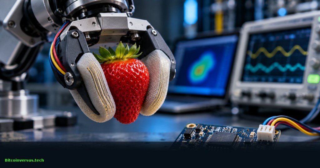
Microchip Technology introduced the ATFCD52 capacitance digitizer on November 10, 2026, promising faster electronic touch measurements for robotic grippers and humanoid hands. The chip accepts up to 52 sensor-electrode channels, arranged as 32 transmit (TX) and 20 receive (RX) lines. Microchip specifies up to 800 complete sensor frames per second for a 10 × 10 array. The announcement concerns a purchasable sensing component, not a commercially proven robot that can independently detect and correct every slipping grip.
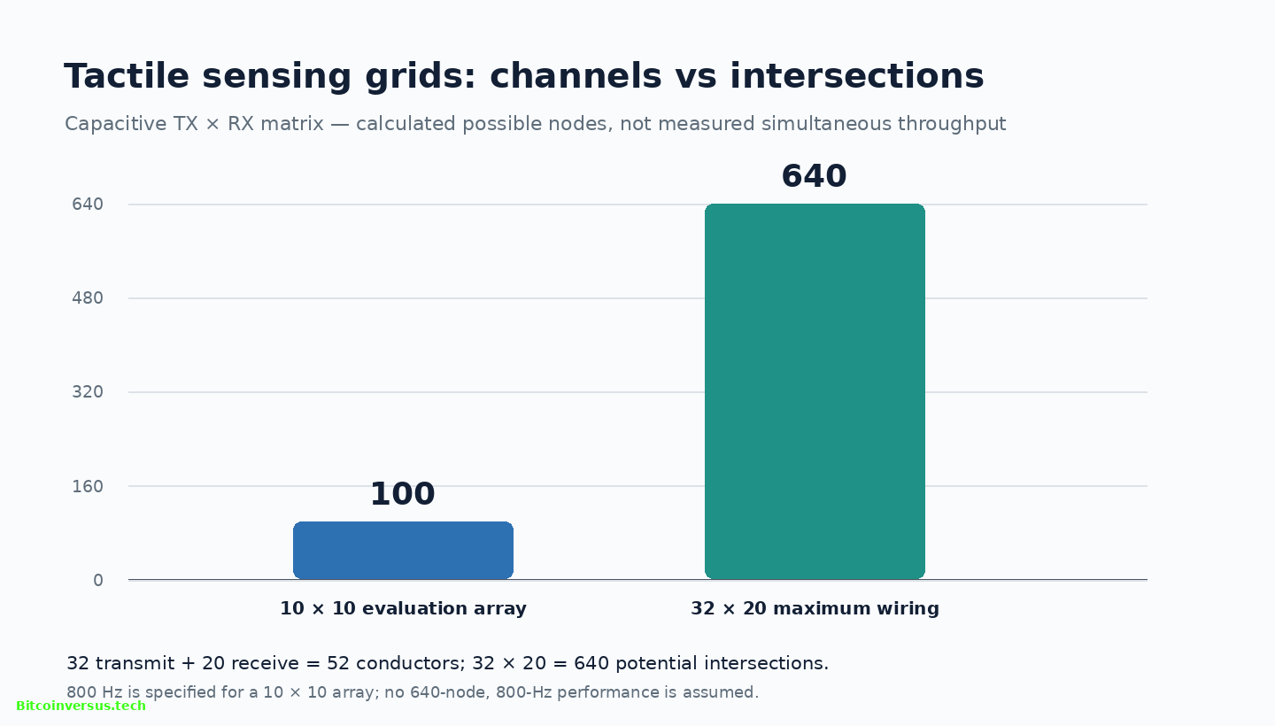
Fifty-two connections can address more than 52 touch locations
Capacitive tactile sensors work by detecting tiny changes in electrical capacitance as flexible material bends or compresses. A two-dimensional matrix uses intersecting TX and RX conductors. For Microchip’s supplied 10 × 10 evaluation array, simple multiplication gives 100 potential sensing intersections. Wiring all 32 TX and 20 RX lines could theoretically address 640 intersections, 6.4 times the evaluation-array count. The 52 figure describes conductor channels, not a limit of 52 independent contact pixels.
Microchip says 20 parallel analog front ends acquire the receive lines simultaneously. However, its advertised 800-Hz rate is tied to a 10 × 10 matrix; no verified 800-Hz performance claim is available for the maximum 32 × 20 configuration. Array dimensions, noise filtering, interface throughput and acquisition settings can change effective scan rates. Separate Carnegie Mellon robotic-fingertip research illustrates how tactile measurements can complement mechanical manipulation rather than replace it.
A 1.25-millisecond frame is not a 1.25-millisecond reaction
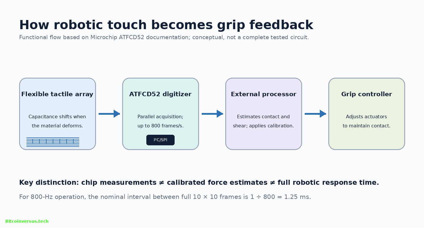
At 800 frames per second, one nominal frame interval lasts 1 ÷ 800 second, or 1.25 milliseconds. The result describes how often digital capacitance maps could be delivered under the specified conditions. Mechanical response takes longer: software must interpret contact patterns, estimate normal and shear forces, issue commands and move actuators. Claiming a complete 1.25-millisecond anti-slip reaction would wrongly treat acquisition time as total feedback-loop latency.
Microchip specifies sensitivity to changes smaller than one femtofarad, equivalent to less than 10⁻¹⁵ farad. That measures capacitance resolution, not an independently calibrated force threshold. Sensor geometry, material thickness, temperature, pressure distribution and calibration determine what the readings mean physically. In a July peer-reviewed Sensors study, researchers tested a different three-element capacitive fingertip module and reported useful relative contact patterns, while explicitly distinguishing the observations from calibrated force measurements.
Noise suppression and prototype integration remain engineering tests
Electrical interference can corrupt tiny capacitive changes. Servo motors, switching power electronics and voltage regulators generate disturbances near sensing circuitry. The ATFCD52 uses frequency hopping and oversampling to mitigate interference, according to Microchip. Actual performance across motor loads, different elastomer materials, changing temperatures and full robot-duty cycles has not been independently established. Related Panasonic touch-based manipulation research examines the much broader software challenge of turning tactile observations into useful actions.
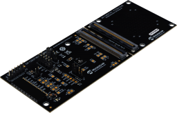
Microchip’s EV-ATFCD52 development kit includes a 10 × 10 capacitive array, sensor material and a connector for custom arrays. The documentation specifies a separate USB High Speed Bridge Board V2 for I²C configuration and SPI frame-data capture; the bridge is not included with the kit. Microchip offers configuration and logging software so engineers can compare sensor stack-ups and tune noise behavior before implementing closed-loop control.
Commercial applications could include robot fingers, sensing gloves, wearable electronic skin and gaming accessories, but Microchip has not disclosed independent robot-level slip-prevention success rates, customer deployment counts or a universal force-calibration standard for its new device. Earlier BitcoinVersus.Tech reporting on human-motion and tactile training data, dexterous robot hands and touch-and-motor-control projects highlights the integration gap. The verified milestone is a commercially available high-speed digitizer and evaluation path; repeatable grip outcomes still require complete-system testing.
Sources and method: Microchip announcement, November 10, 2026; Microchip ATFCD52 specifications; Microchip EV-ATFCD52 evaluation-kit documentation; Kwon et al., Sensors, July 27, 2026 (independent capacitive sensing research involving a different device); Robotics Business News, November 11, 2026. Original calculations: 10 × 10 = 100; 32 × 20 = 640; 640 ÷ 100 = 6.4; 1 ÷ 800 Hz = 1.25 ms. Values are specified maxima, not independently measured robotic throughput.
Editor’s Note: Microchip’s 52 channels, 32-TX/20-RX matrix, 800-Hz maximum for a 10 × 10 array, and sub-femtofarad sensitivity are manufacturer-reported specifications. A 640-intersection matrix is a calculated wiring possibility, not proof of 800-Hz acquisition at that size. A 1.25-ms frame interval is not a measured closed-loop robotic grip response. The July Sensors study concerns a separate research device, not ATFCD52 validation. The cover is conceptual artwork, while the evaluation-board photograph comes from Microchip. No suitable official ATFCD52 YouTube video with verified identity and availability was established; no unverified player was embedded. Real-device responsive checks and live video playback were not performed.

BitcoinVersus.Tech is volunteer-run and publishes independent educational technology reporting. An optional 5,000-satoshi donation supports continued research. Scan the original QR from a second screen using a compatible Bitcoin wallet; on mobile, use a wallet supporting QR scanning from a saved image. Independently verify the recipient address 3C9o19EH5HSiwEPyCTmEKzxhNCbo2X6TTb and the amount before payment. Bitcoin transactions are generally irreversible.
We volunteer daily to ensure information on the BitcoinVersus.Tech platform is Verifiably True. Coverage is for educational and informational purposes and does not constitute financial or investment advice.


Leave a Reply