Elementary Overview
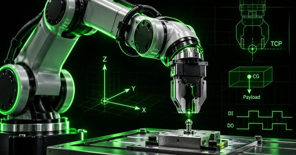
An industrial robot becomes useful when a tool is attached to the end of its arm. That tool is called an end effector, and it can be a gripper, suction cup, welding torch, screwdriver, camera, dispenser, or another device made for the job. The robot also needs to know the exact working point of that tool, called the Tool Center Point (TCP). If the TCP is wrong, the robot may move its arm correctly but still place the actual tool tip in the wrong location. This lesson builds on OSRTC.001 robot safety, OSRTC.002 teach-pendant motion and coordinate frames, and OSRTC.003 mastering and calibration.
End Effectors Are the Robot’s Working Interface
The end effector is the hardware that actually interacts with the process, so a technician must treat it as both a mechanical assembly and a control device. Common grippers include pneumatic parallel grippers, electric servo grippers, vacuum cups, magnetic tooling, and adaptive fingers. Tool selection depends on part geometry, surface condition, required grip force, cycle time, available utilities, contamination limits, and the robot drive system and payload envelope. The tool must be mounted rigidly enough that its geometry does not shift during acceleration, because a loose bracket or flexible adapter changes the real TCP even when the controller’s numbers have not changed.
Mounting, Utilities, and Mechanical Checks Come First
Before teaching software values, verify the physical installation. The tool flange, adapter plate, fasteners, dowel or locating features, cable dress, air tubing, electrical connector, and strain relief must all be correct for the manufacturer’s design. A pneumatic gripper may require compressed air, a solenoid valve, and output wiring; an electric gripper may require 24 VDC power, communication, or digital control. Route cables and hoses so they cannot snag, enter a pinch point, exceed bend radius, or wrap around the wrist. After installation, perform the safe low-speed manual checks described in OSRTC.002 before any automatic test.
The TCP Defines Where the Robot Thinks the Tool Is Working
The Tool Center Point is a position and orientation defined relative to the robot’s tool flange. For a gripper it may be the center between the fingertips; for a welding torch it may be the wire tip; for a dispenser it may be the nozzle outlet. In transformation form, the controller conceptually combines the robot flange pose with the tool transform: BTTCP = BTF × FTTCP. This is why the coordinate-frame and kinematics concepts used by robot engineers still matter to technicians: a wrong tool transform shifts every point programmed with that tool.
Teach the TCP From Multiple Tool Orientations
A common TCP calibration method touches the same fixed reference point from several different tool orientations. The controller uses those poses to solve for the point on the tool that remains geometrically common while the wrist rotates. Greater orientation diversity normally improves the geometry of the calculation; repeated poses that are almost identical provide weak information. After position is taught, tool orientation may also need to be defined so the tool’s X, Y, and Z axes match the intended process direction. A correctly mastered robot can still have a wrong TCP, so joint mastering and tool calibration must be verified separately.
Payload, Center of Gravity, and Inertia Must Match the Real Tool
The controller also needs the mass properties of the end effector and anything it carries. Payload mass is not enough by itself: the center of gravity (CoG) tells the robot where that mass is located, and some controllers also use the payload inertia matrix. The basic mechanical reason is torque: τ = r × F, with F = mg. A heavier tool or a long CoG offset creates more joint torque than the same mass close to the flange. Incorrect payload data can reduce motion quality, trigger protective stops, distort force sensing, or create unsafe behavior. Universal Robots’ current guidance requires accurate mass, CoG, and inertia values and recommends updating them when a workpiece is picked up or released.
Grippers Need I/O Commands and Feedback, Not Just Motion
Many end effectors are controlled through digital outputs and verified with digital inputs. A simple pneumatic sequence can be: command the close output, wait for a closed or part-present input, then permit the robot to move. The safe control idea is a handshake rather than a blind delay. For example: DO_GRIP_CLOSE = ON → WAIT DI_GRIP_CLOSED = ON → MOVE. More advanced tools may use analog signals, fieldbus communication, serial links, or robot software plugins. The same troubleshooting habits used for industrial signal scaling and serial interfaces apply here: confirm power, pinout, signal state, command path, and feedback independently before blaming robot motion.
Verify the Tool Before Returning the Cell to Automatic Production
A tool setup is not complete when the controller accepts the numbers; it is complete when the physical behavior is independently verified. Jog the active TCP around a fixed reference point and rotate the wrist: the calibrated point should remain stationary within the expected accuracy. Then test open/close commands, feedback inputs, payload state changes, cable clearance, approach positions, and a reduced-speed dry run. If a tool is replaced, repaired, bent, remounted, or changed by wear, recheck the TCP. If errors appear everywhere, investigate the tool frame or mastering; if only one fixture is shifted, investigate the work frame; if only grip confirmation fails, investigate I/O and the end effector. This layered fault isolation prevents technicians from “fixing” geometry by reteaching production points unnecessarily.
Technician Setup Checklist
- Apply the workcell safety procedure from OSRTC.001.
- Confirm the correct robot, controller, end effector, adapter, and manufacturer documentation.
- Inspect the tool flange, fasteners, locating features, cables, hoses, connectors, and strain relief.
- Confirm utilities: air pressure, vacuum source, electrical power, communication, and grounding where required.
- Jog at reduced speed and verify mechanical clearance through the required wrist orientations.
- Teach or enter the TCP position using the manufacturer-approved method.
- Teach tool orientation if the process requires a defined tool-axis direction.
- Enter payload mass, center of gravity, and inertia when supported.
- Map outputs that command the tool and inputs that confirm tool state.
- Verify the TCP against a fixed reference from multiple orientations.
- Test gripper open/close or tool on/off functions without a production part first.
- Test with the real workpiece and confirm payload changes or grip feedback.
- Dry-run the program at reduced speed with adequate clearance.
- Save a verified controller backup containing tool, payload, frame, and I/O data.
Worked Example: Parallel Gripper Pick
- Tool: electric or pneumatic parallel gripper.
- TCP: center between the fingertips at the intended gripping depth.
- Empty-tool mass: 2.0 kg.
- Part mass: 1.5 kg.
- Loaded payload: 3.5 kg plus the correct combined CoG.
- Command: set gripper-close output or tool command.
- Feedback: wait for gripper-closed or part-detected input before retracting.
- Verification: jog the TCP around a fixed pointer, rotate the wrist, confirm the point stays centered, then execute a low-speed pick-and-place dry run.
Exercises
- Choose a hypothetical gripper and identify its mounting, power, air, communication, and I/O requirements.
- Draw the tool flange frame and a TCP frame located 150 mm along the tool Z axis.
- Explain what happens to every taught position if the TCP Z offset is entered 10 mm too long.
- For a 3 kg tool whose CoG is 0.20 m from the wrist axis, estimate the gravitational moment magnitude using τ ≈ rmg.
- Write a basic gripper handshake using one digital output and one digital input.
- List three reasons a TCP may change even though the robot has not lost mastering.
- Describe how you would separate a TCP error from a work-frame error.
- Explain why a fixed time delay is weaker than confirmed gripper feedback.
- Create a post-tool-change verification checklist suitable for a maintenance work order.
Knowledge Check + Answers
- What is an end effector? The tool attached to the robot wrist or tool flange that performs the process interaction.
- What is the TCP? The controller-defined working point and orientation of the active tool relative to the tool flange.
- Why use several orientations when teaching TCP? Multiple distinct orientations give the controller enough geometric information to solve the tool offset more accurately.
- Can correct mastering guarantee a correct TCP? No. Joint mastering and tool calibration are separate references.
- Why does center of gravity matter? A mass farther from the flange produces more torque and changes the robot’s dynamic behavior.
- What is a basic I/O handshake? Command an output, verify the expected input feedback, then permit the next motion.
- What should be checked after replacing a gripper? Mechanical mounting, cables or hoses, TCP, orientation, payload/CoG, I/O, clearance, and reduced-speed program behavior.
- Why avoid reteaching every program point when one tool changes? Correcting the tool definition preserves programs that were originally taught correctly and fixes the shared root cause.
Elementary Conclusion
A robot arm can know exactly where all of its joints are and still miss the job if it does not know the shape and behavior of the tool on its wrist. The end effector is the robot’s “hand,” while the TCP is the exact point on that hand that the controller tries to place. The payload tells the robot how heavy the tool and part are, the center of gravity tells it where that weight is pulling, and I/O signals tell the gripper when to open, close, and report success. A technician therefore checks the whole chain—mechanical mounting, TCP, payload, wiring, feedback, and safe motion—rather than treating the gripper as a simple accessory. That is the practical bridge from the manual positioning of OSRTC.002 and the joint accuracy of OSRTC.003 to a robot that can actually pick, place, weld, dispense, or assemble correctly.
BitcoinVersus.Tech
Advertisement
Editor’s Note:
We volunteer daily to ensure the credibility of the information on this platform is Verifiably True. If you would like to support our research initiatives, please donate here: 3C9o19EH5HSiwEPyCTmEKzxhNCbo2X6TTb
BitcoinVersus.tech is not a financial advisor. This media platform reports on financial subjects purely for informational purposes.


Leave a comment